Surge and Lightning Protection for DC Fast Chargers: Where Site Designs Go Wrong
Home / Blog / Guidelines / Surge and Lightning Protection for DC Fast Chargers: Where Site Designs Go Wrong
03 Nov, 2026
800V DC bus surge protection
DC SPD selection
EV charger lightning protection
surge protection device for EV charger
Type 1 vs Type 2 SPD
Most DC fast charger failures blamed on lightning are not lightning failures. They are specification failures: the site has an AC surge protection device at the feeder, nothing on the DC output bus, and a bonding path that was never designed. A DC fast charger needs two coordinated protection zones, one on each side of the power conversion stage, and neither works if the equipotential bonding is wrong.
Key takeaways
A DC fast charger has two protection zones, the AC feeder upstream of the rectifier and the DC output bus downstream of it, and an SPD clause copied from an AC wallbox specification covers only the first.
Choose Uc for the highest sustained voltage the bus can reach, including an input window that puts a 380 V nominal three-phase supply at 437 V at the top, not for the nominal label on the drawing.
A DC arc has no zero crossing, so a device holding an AC certificate to IEC 61643-11 is not validated for DC service and should be asked for on DC test evidence.
Residual voltage at the equipment is the protection level plus whatever the connecting leads develop, so bonding geometry and lead length decide whether a correctly rated SPD does anything.
An SPD that fails silently keeps the site billing and unprotected, which makes a status contact wired to the controller worth more than a larger advertised discharge rating.
The Two-Zone Blind Spot: Why Most DC Fast Charger Surge Failures Start in the Spec
An AC SPD at the distribution board plus an unprotected DC output bus is the standard configuration on a large share of DC fast charging sites, and it is the configuration that fails. That is not bad luck with weather. It is a line item that never made it into the bill of materials.
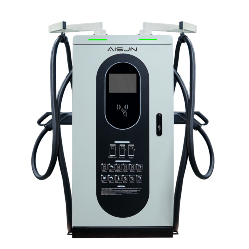
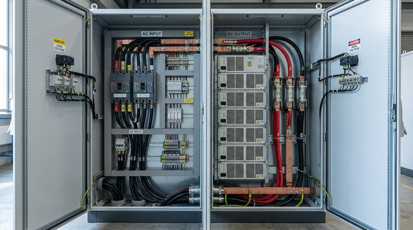
Name the two zones precisely. Zone one is the AC feeder side, upstream of the rectifier: the charger input, the EMI filter, the auxiliary supply. Zone two is the DC output bus, downstream of the rectifier: the power modules, the DC bus capacitance, the output contactor, the metering, and through the cable, the vehicle inlet. AiPower’s DC EV Charger range runs from 30 kW to 480 kW on a 380 V plus or minus 15% three-phase input, so both zones exist in every unit regardless of power level, and both scale with it.
What sits on the unprotected side is expensive. Power modules, DC bus capacitors, output contactors, energy metering and the vehicle’s own charging electronics all see the transient, and the least robust component in that chain sets the failure point. Module replacement is the cost driver that modular versus monolithic DC charger architecture decides, and a surge event is a hard way to find out which one you bought.
Built-in protections do not close the gap. The 8-layer protection set on a DC charger covers over-current, under-voltage and the rest, and every one of those functions responds to a condition that already exists. A transient front is over before the controller has finished sampling it.
So why does the gap exist? Procurement language is copied from AC wallbox specifications. An SPD clause written as a Type 2 device at the board is carried into a 200 kW project unchanged, nobody owns the space between the two zones, and the DC side ships bare.
The commercial argument needs no invented figures: unplanned downtime, a truck roll, a module replacement and the SLA exposure of a dead site during a peak window. The SPD line is the smallest number in that comparison and the only one a buyer controls in advance. That is why the rest of this article stays on the DC side rather than on EV surge protection in general.
Interior of a DC fast charger cabinet showing the AC input side and the DC output bus as two separate compartments
What a Surge Protection Device Actually Does (And What It Cannot Absorb)
A surge protection device is a voltage-controlled switch, not a filter and not a sponge. At normal operating voltage it presents high impedance and does nothing. When the voltage across it rises past its threshold it becomes close to a short, diverting surge current around the load and clamping the voltage the load sees. It survives by spreading energy across time and across parallel paths, so the aim is diversion, not absorption.
Four datasheet numbers decide whether the device protects anything:
Continuous operating voltage (Uc). The highest sustained voltage the device can sit at without degrading.
Protection level (Up). The residual voltage that still reaches the equipment while the device is conducting. This is what the power modules and the vehicle inlet actually experience.
Nominal and maximum discharge current (In and Imax). Measured on an 8/20 microsecond waveform. In is what the device takes repeatedly, Imax is the single hit it can survive once.
Short-circuit current rating. What the device can survive if it fails in a location with high prospective fault current, and the number that must be coordinated with its backup fuse or breaker.
Direct-strike capability is a separate question. A 10/350 microsecond impulse rating is what separates a Type 1 device at a service entrance from a Type 2 device downstream. A site that needs both does not get both by buying a larger Type 2.
Read Type 1, 2 and 3 by location rather than by catalogue name. Type 1 sits where lightning current may enter, at the service entrance. Type 2 sits at a distribution board where the residual wave arrives. Type 3 sits at the point of use for the last few hundred volts of clamping.
The surge sources matter because they set exposure: direct and nearby lightning, utility grid switching and capacitor bank operations, load switching and inductive kickback from motors and compressors on the same site, ground potential rise from a strike hundreds of metres away, and fault conditions inside the installation. A front that arrives in microseconds is largely over before a breaker or fuse has begun to move, which is why the SPD is a separate device and not a substitute for overcurrent protection.
Then there is wear. A metal oxide varistor that clamps many small events drifts, its leakage current rises, and it can reach end of life with no visible fault until the event that matters. A higher advertised joule count does not make a protector safer for a charger either. Uc, Up and the fault current rating decide the outcome.
Why DC Is a Harder Protection Problem Than AC
Direct current has no zero crossing. Alternating current passes through zero every half cycle, and that zero is what extinguishes an arc drawn during a switching or fault event. A DC arc sustains for as long as current flows and the voltage stays above the level needed to keep the plasma alive. Everything else about DC protection follows from that single fact.
Device design changes accordingly: DC-rated arc quenching, magnetic blowout or wider contact gaps, DC fuses with the right time-current curve, and DC breakers genuinely rated for the bus voltage rather than an AC device with a DC figure printed on the side.
Continuous stress is the second difference. A DC bus SPD sits at a high Uc all day with no relief, so thermal design and leakage current matter more than on an AC device that passes through near zero volts twice per cycle.
Topology adds a third. An earthed DC bus and a floating DC bus need different treatment. On a floating bus an insulation monitoring device watches for loss of isolation, and a leaky SPD or a filter capacitor to protective earth can irritate or blind that monitor. The protection problem quietly becomes a nuisance alarm problem that nobody can close out.
Arc containment inside the cabinet belongs to the protection scheme, not to cosmetics. A DC fault has no natural extinction point, so barriers, separation distances and enclosure design are doing safety work.
What Is a DC SPD and What Is Its Purpose?
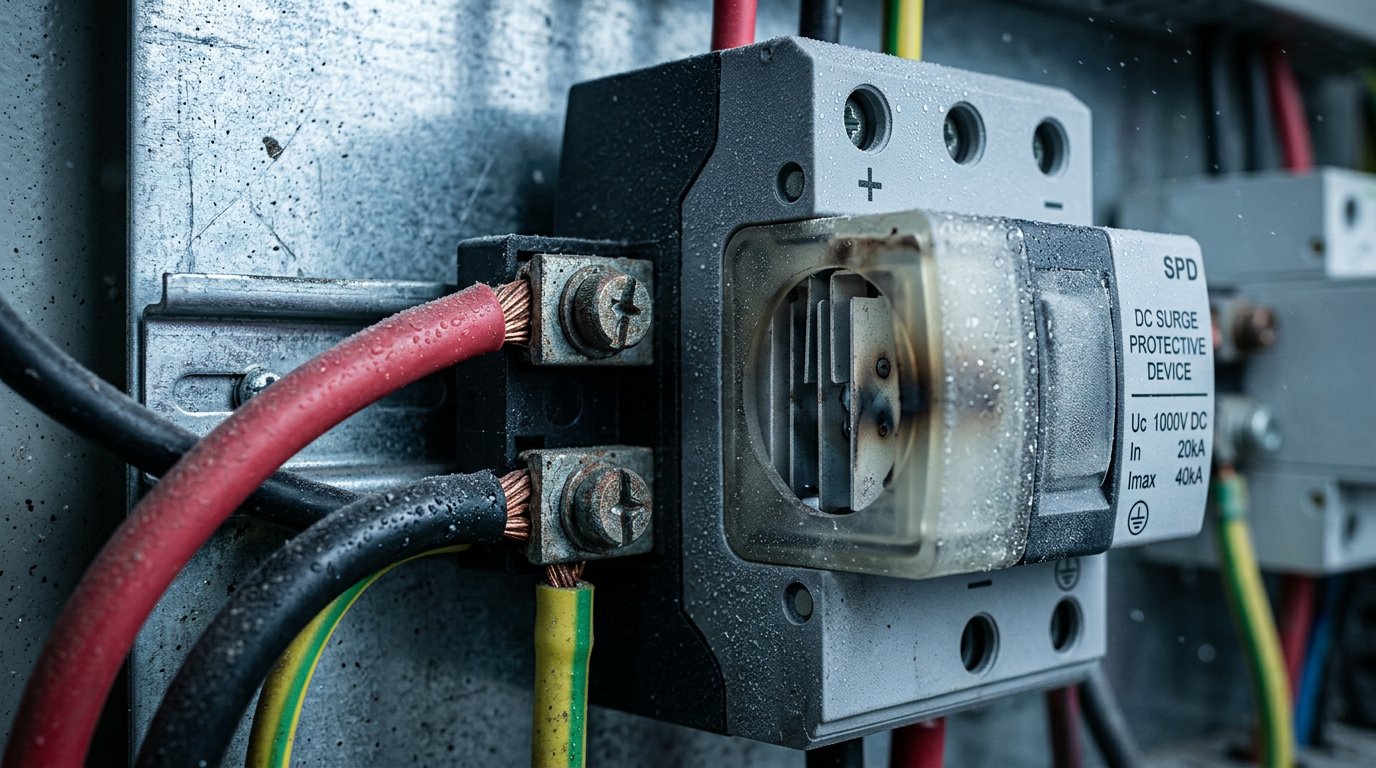
It is a surge protective device evaluated and rated for direct voltage service at a stated bus voltage, installed to clamp transients on the DC side of the conversion stage. Its purpose is to stop the power modules, the bus capacitance and the vehicle inlet from becoming the clamp instead.
The practical consequence is blunt: an SPD holding an AC certificate to IEC 61643-11 is not automatically validated for DC service at your bus voltage, and a datasheet listing only AC ratings is not a DC specification. Ask for a DC voltage rating at or above the architecture class, a stated DC discharge capability, and evidence the device was evaluated on DC rather than inferred from AC test data.
DC-rated surge protection device with heavy conductors mounted on a metal backplate
Matching the SPD to the DC Bus: 400 V, 800 V and 1000 V Architectures
Selection starts with one rule: pick Uc for the highest sustained voltage the bus can reach under any normal condition, including supply tolerance and the temperature derating the manufacturer publishes. A device chosen at exactly nominal is a device chosen to degrade.
The same logic applies on the AC side, where the mistake is quieter. A charger specified at 380 V three-phase with a plus or minus 15% input window can sit at 437 V at the top of that window, so the AC SPD’s Uc has to be chosen for the top, not for the label. Sites with weak supplies and recurring three-phase power quality problems that damage DC fast chargers spend a lot of time up there.
Then the three architecture classes. A 400 V class bus, an 800 V class bus and a 1000 V class bus each imply a different Uc, and the margin above the class maximum is the whole point of the exercise. A 400 V class device cannot be carried onto an 800 V platform, and an 800 V device on a 1000 V platform is exactly as wrong.
Protection level is the second constraint and it is independent of Uc. Up must sit below what the downstream components withstand at their most sensitive point. Two components set that ceiling: the power modules’ DC bus and the vehicle’s input stage. The vehicle side is defined by the DC output characteristics in the applicable charging standard, not by the charger alone. When Up is too high, the silicon clamps instead of the SPD.
Discharge capacity should match exposure, not a bigger number. A sheltered urban canopy, an exposed coastal or open-field site, and a site with tall structures or a history of nearby strikes sit in different exposure classes. Buying on the highest advertised maximum discharge current is not a selection method.
Short-circuit current rating completes the set. The device must survive the prospective fault current at its own installation point, and it must be backed by a protective device whose let-through energy it can take. That coordination is a tested property of the pair. Three documents answer three different questions: IEC 61643-11 covers the device, IEC 61643-12 covers selection and application, IEC 62305 covers the lightning protection context around the site.
One Device, Two Approval Files
IEC 61643-11 and UL 1449 classify and mark the same physical product differently, with their own type designations, test waveforms and short-circuit marking conventions. For a programme shipping to several regions, write Uc, Up, discharge rating and fault current rating into the requirement, then ask for the certificate per market. One certificate is not evidence for the other. The charger beside it deserves the same discipline: AiPower’s solutions hold UL and CE certifications, and the file should match the market on the shipping label.
Six questions carry the whole supplier conversation: bus class, highest sustained voltage, required Up, expected exposure, available fault current, and the approval file for each market.
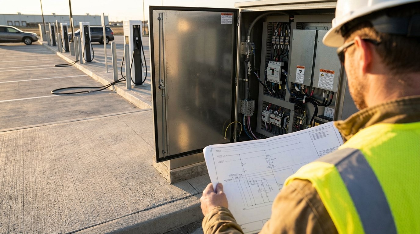
Engineer comparing a site single-line drawing with an open DC charger cabinet at a charging site
Follow the Surge: How Energy Divides Between the AC Feed, PE and the DC Cable
There are three coupling routes and they need different mitigation. Conducted surge arrives on the AC conductors, in differential mode between phases and in common mode from conductors to earth. Ground potential rise arrives on the protective earth itself. The DC output cable and the connected vehicle act as a third path, one that no AC-side drawing shows.
Common mode is the killer. Current arrives on the phase conductors and must leave via the protective earth, so the clamping path and the bonding impedance sit in series with the equipment being protected. A perfect SPD on a poor bonding path delivers nothing.
Picture a session in progress. The vehicle chassis is bonded to the charger’s protective earth through the connector, so a strike near the vehicle places the DC cable inside the loop. Both the vehicle’s charging electronics and the charger’s output stage see the resulting potential difference, one from each end of the same conductor.
Once there is a coordinated pair, energy divides instead of doubling up. The upstream device takes the bulk of the conducted energy. Whatever remains, plus anything coupled in downstream of that point, lands on the DC-side device. That is why two SPDs are coordination rather than duplication.
The mechanism sets the rules. The upstream device needs the higher discharge capacity because it takes the bulk. The downstream device needs the lower protection level because it clamps what is left. The cable between them needs enough length that the downstream device does not receive the whole wavefront at once. Separation distances are not convention, they are a consequence of where the energy lands.
Lead inductance is why placement rules exist at all. Residual voltage at the equipment is the device’s protection level plus the voltage developed across its connecting leads while surge current flows. Long or looped leads add impedance and quietly undo a well-chosen Up.
With no DC-side device, the surge finds the power modules’ switching devices and the DC bus capacitors, which behave as the least robust clamp in the circuit. The failure gets logged as a module fault, not as a surge, which is exactly the misdiagnosis described at the start. And a site with two SPDs of unknown ratings counts as a site with no coordination.
Bonding and Grounding: The Part That Decides Whether Any SPD Works
Everything else rests on one principle: the SPD diverts current, and diversion only happens if the return path has lower impedance than the path through the equipment. Bonding is how that condition is met.
Ground potential rise makes it concrete. A large surge current flowing through a finite earth impedance lifts the local reference, so the equipment does not see what the SPD clamps at. It sees the difference between two points that were assumed to be the same point.
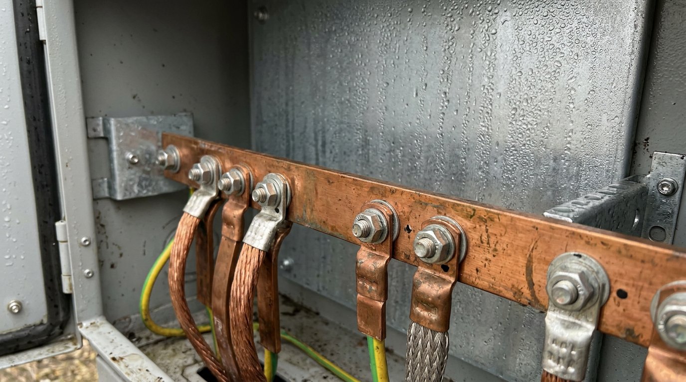
What has to be bonded together: cabinet frame and doors, connector body, cable armour or shield where fitted, the site earth bar, and any other metallic service entering the cabinet. Bonding only the electrical earth and leaving the rest floating is the classic gap.
Routing is part of the same problem. Short, straight, wide conductors, no loops, the manufacturer’s specified lead length respected, pre-formed busbars where supplied. Wide and short beats thick and long, because at surge frequencies impedance is what matters.
Which is why a low earth resistance reading does not prove the bonding is adequate. A long thin conductor can read acceptably on a DC earth test and behave badly under a fast wavefront.
The recurring installation errors, each with its reason: a dedicated earth rod for the charger, which creates a second reference for current to flow between; daisy-chained protective earth through several cabinets, which adds impedance at every hop; a bond made through a painted gland plate, which is not a bond; a separate clean earth for electronics, which reintroduces the potential difference the scheme exists to remove; and a bonding conductor sized for continuous current instead of surge current.
One diagnostic difference is worth carrying into the field. An intermittent fault pattern spread across several unrelated subsystems points at a reference problem. A single subsystem failing points at that subsystem.
So put bonding on the electrical drawing and in the commissioning checklist. Left in the electrician’s scope by default, it gets whatever is quickest, and the energy does not wait for a scope debate.
Copper equipotential bonding busbar with short wide conductors inside an outdoor electrical cabinet
Inside the Cabinet: Placement, Backup Protection and How an SPD Fails
Placement decisions inside the cabinet are usually made by whoever draws the layout, which means they are often made by accident. Each of these needs a stated answer in the specification.
AC main disconnect. An SPD ahead of the disconnect protects the cabinet but is not isolated by it. One downstream is isolated for service but leaves the incoming feed unprotected. Both are legitimate, and the drawing rarely says which one you are getting.
DC output contactor. A DC-side SPD downstream of the contactor protects the bus only while the contactor is closed. One placed upstream protects continuously but sits on a live bus during service. That is a service decision, not a layout preference.
Backup protection. SPDs typically fail short, so a dedicated backup fuse or breaker is required, rated to the device’s fault current capability and slow enough not to operate on legitimate surge current. The coordination is a tested pair property, and a different fuse fitted later breaks it.
Failure modes. Gradual end of life from varistor degradation, thermal disconnect opening and taking the device out of circuit, short-circuit failure, and the silent failure where the status indicator changes state and nobody is scheduled to look.
Why silent failure is worse. The site stays online and keeps billing, so nothing triggers a visit. It runs unprotected until the event it was bought for, and then the whole cabinet goes down instead of one field-replaceable part.
Status contacts. A volt-free contact wired back into the controller turns end of life into an alarm on the operator’s dashboard instead of a post-mortem discovery. Replaceable cartridges turn the repair into a swap rather than a cabinet return.
Outdoor reality. Condensation on a device that is cold soaked and then energised, thermal cycling loosening terminal torque season after season, the enclosure’s ingress protection versus the device’s own, arc containment and separation in a small space, and terminal corrosion in coastal air.
A status indicator is the minimum. It only earns its place if it reports somewhere, and that reporting gap is the real difference between a consumer strip protector and a device specified for a charging network.
Commissioning and Maintenance: What to Measure and What the Symptoms Mean
Commissioning is where a specification either becomes a protected site or a folder of paperwork. Run these in sequence.
Confirm the installed device matches the specified Uc for the bus class, and record it. Substitutions happen.
Record the protection level actually supplied, not the one in the tender.
Verify bonding continuity end to end with a low-resistance measurement between cabinet, connector body and the earth bar.
Confirm the status indicator is intact and the remote contact is wired and reporting.
Record terminal torque values so the next visit has a reference.
Take a baseline insulation reading on the DC bus with the charger isolated. On a floating bus this also shows whether a leaky device is already loading the insulation monitoring function.
Confirm the backup protective device is the rating the SPD manufacturer coordinated with, not whatever was on the van.
Interval checks stay short and physical: status indicator and remote alarm state, terminal torque, any discolouration or tracking around the device, signs of water ingress, and whether the fitted device is still the original part after any field repair.
The three-way symptom distinction is what you will actually face. An SPD at end of life shows a status or alarm change while the site otherwise performs normally. A bonding failure shows intermittent faults across several unrelated subsystems, communication errors and odd touch-potential reports. A genuine surge event shows failures clustered in time across multiple sites or multiple subsystems after a weather event.
Then there is the question owners ask after every outage. A mains failure is not a surge, but the switching transient when supply returns is, and a site whose protection is at end of life is at its most vulnerable at exactly that moment. That is the practical answer to a worry that sends a lot of people searching in the first place.
Hold a spare cartridge and the correctly rated backup fuse. Fitting an unrated or different-brand device in the field converts a protected site into an unprotected one while looking identical on the asset register. Record the device model, its Uc and Up, the date fitted and the last measured bonding resistance, or the next inspection has nothing to compare against.
What to Change in Your Next Specification
Three edits to the next bill of materials and RFQ do most of the work.
Write a DC-side requirement. Name the bus voltage class, the required continuous operating voltage and the protection level. Leaving it implied by an AC-side clause is how the DC bus ends up bare.
Require a status contact. Specify that the DC-side device reports to the site controller. An unmonitored SPD is an assumption, not a protection measure.
Put bonding on the drawing with a measurable acceptance criterion, so it becomes a commissioning item rather than an installer’s judgement call. The EV charger RFP procurement checklist for fleet and site operators is a reasonable place to start writing the clause.
Four lines carry the requirement to any supplier: bus class, highest sustained voltage, required protection level, available fault current. Add the approval file for each market being shipped to, and quotes can finally be compared on equal terms.
On the charger side of the scheme, evaisun’s DC range covers 30 kW to 480 kW on a 380 V plus or minus 15% three-phase input, with an 8-layer internal protection set and UL and CE certification, built by a team that includes more than 60 engineers. Those internal protections are the last line. The DC-side device is the first. Send us your site class and bus voltage and we will tell you what the DC side needs, before it turns into a module replacement.
Frequently asked questions
Do I need a Type 1 or Type 2 SPD for a DC fast charger?
It depends on location, not preference. Type 1 belongs where lightning current may enter, such as a service entrance on a site with an external lightning protection system. Type 2 sits at the distribution board downstream. On the DC bus the Type designation is less useful than the DC voltage rating, so specify Uc at the bus class and ask for DC test evidence.
Why does an SPD fail without tripping the breaker?
Most SPD failures are not short circuits. A metal oxide varistor degrades gradually, its leakage rises, and an internal thermal disconnect takes the cartridge out of circuit before anything trips. The site keeps running with no protection until the status window or remote contact shows the change. That is why an unmonitored device is an assumption.
Is a whole house surge protector enough for an EV charger?
No. A service-entrance device takes the bulk of the energy but leaves the residual wave and anything coupled downstream to reach the charger. A DC fast charger also needs a DC-side device on the output bus, plus short connecting leads and correct equipotential bonding. Protection is a coordinated set of zones, not one box at the panel.
How do you know if an EV charger is AC or DC?
Check where the AC to DC conversion happens. An AC charger hands alternating current to the vehicle and relies on the onboard charger, which caps power at what that converter can take. A DC fast charger rectifies inside the cabinet and feeds the battery directly, which is why it has a DC output bus to protect.
Can one SPD protect both the AC and DC side of a charger?
No. The two sides differ in voltage class, prospective fault current and failure consequence, so they need separate devices. The AC device clamps the incoming wave; the DC device clamps what remains plus anything coupled onto the output cable. Treating one device as cover for both sides is how the DC bus ends up unprotected.
Subscribe the newsletter to get updated to news and promotions
Cookies give you a personalized experience,Сookie files help us to enhance your experience using our website, simplify navigation, keep our website safe and assist in our marketing efforts. By clicking "Accept", you agree to the storing of cookies on your device for these purposes. Click "Adjust" to adjust your cookie preferences.For more information, review our Cookie Policy