Solar-Integrated EV Charging: Sizing PV-Coupled Systems Without Oversizing Inverters
Home / Blog / Buyer Education / Solar-Integrated EV Charging: Sizing PV-Coupled Systems Without Oversizing Inverters
31 Aug, 2026
DC-coupled solar charging
inverter sizing EV charging
PV-coupled EV charger
solar EV charger design
The right way to size a PV-coupled EV charging inverter is to match it to the site’s actual peak charging demand curve, not to the total wattage of the solar array sitting on the roof. Most designers oversize the inverter by 20-40% because they size it to PV capacity — and that oversizing shows up later as clipped output, wasted capital, and a poor payback period. Get the DC:AC ratio and load-matching right up front, and you avoid both undersized bottlenecks and expensive dead capacity.
Why ‘Match the Inverter to the Panels’ Is the Wrong Rule
Here’s a mistake we see constantly in RFPs: a contractor specs 100 kW of PV panels, then specs a 100 kW inverter to match. Sounds logical. It’s actually backwards, and it costs money.
Solar panels almost never produce their rated wattage. Between temperature derating, angle-of-incidence losses, soiling, and the fact that peak sun hours only happen for a few hours a day, a 100 kW array typically produces 75-85 kW at its absolute best moment. Sizing the inverter to the full 100 kW nameplate means that inverter sits underutilized for 95% of its operating life.
The industry-standard fix is the DC:AC ratio — oversizing the PV array relative to the inverter, not the other way around. A ratio of 1.2 to 1.4 (meaning 120-140 kW of panels feeding a 100 kW inverter) is common in utility-scale solar and works just as well for EV charging sites. You lose a small sliver of peak production to clipping on the sunniest days, but you gain a smaller, cheaper inverter that runs closer to its efficient operating range all day long.
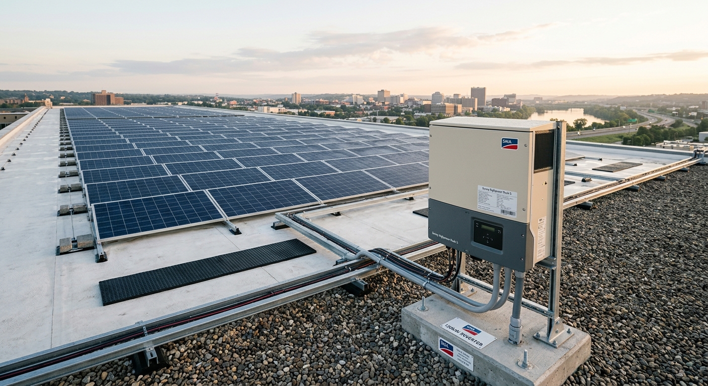
Solar panel array on commercial rooftop with inverter cabinet
AC-Coupled vs. DC-Coupled: Where the Real Efficiency Gains Sit
The architecture decision matters more than most spec sheets suggest. In an AC-coupled system, solar power is inverted to AC, run through the site’s electrical panel, and then rectified back to DC inside the charger. That’s two conversion stages, and each one bleeds a few percentage points of efficiency.
DC-coupled systems skip a step. Solar DC output feeds directly into a shared DC bus that also feeds the charger’s DC output stage — no round trip through AC. The efficiency difference is real: 92-94% for AC-coupled versus 97-98% for DC-coupled setups, measured end to end from panel to vehicle.
When AC-Coupling Still Makes Sense
DC-coupling isn’t always the answer. If you’re retrofitting solar onto a site that already has AC-connected DC chargers — the kind covered in our breakdown of DC charger power module architecture — ripping out the electrical infrastructure to build a shared DC bus rarely pencils out. AC-coupling lets you bolt solar onto existing service with a standard hybrid inverter, and the efficiency loss is often smaller than the capital cost of a full DC-bus redesign.
Size to the Load Curve, Not the Roof
A fleet depot charging 30 delivery vans overnight doesn’t need solar sized around noon peak production — it needs the inverter and any battery buffer sized around when vehicles are actually plugged in. That’s the core sizing principle that gets skipped.
Pull the site’s actual charging demand profile before touching an inverter spec sheet. For a depot following the patterns in our overnight fleet charging design guide, most demand hits between 8 PM and 5 AM — hours when solar production is zero. In that case, PV isn’t offsetting charging load directly at all; it’s offsetting grid draw during daytime operations or charging a buffer battery for later use.
Compare that to a retail or workplace charging site where vehicles plug in during business hours, and PV production overlaps almost perfectly with charging demand. Same solar capacity, completely different inverter sizing logic, because the coincidence between generation and consumption changes everything.
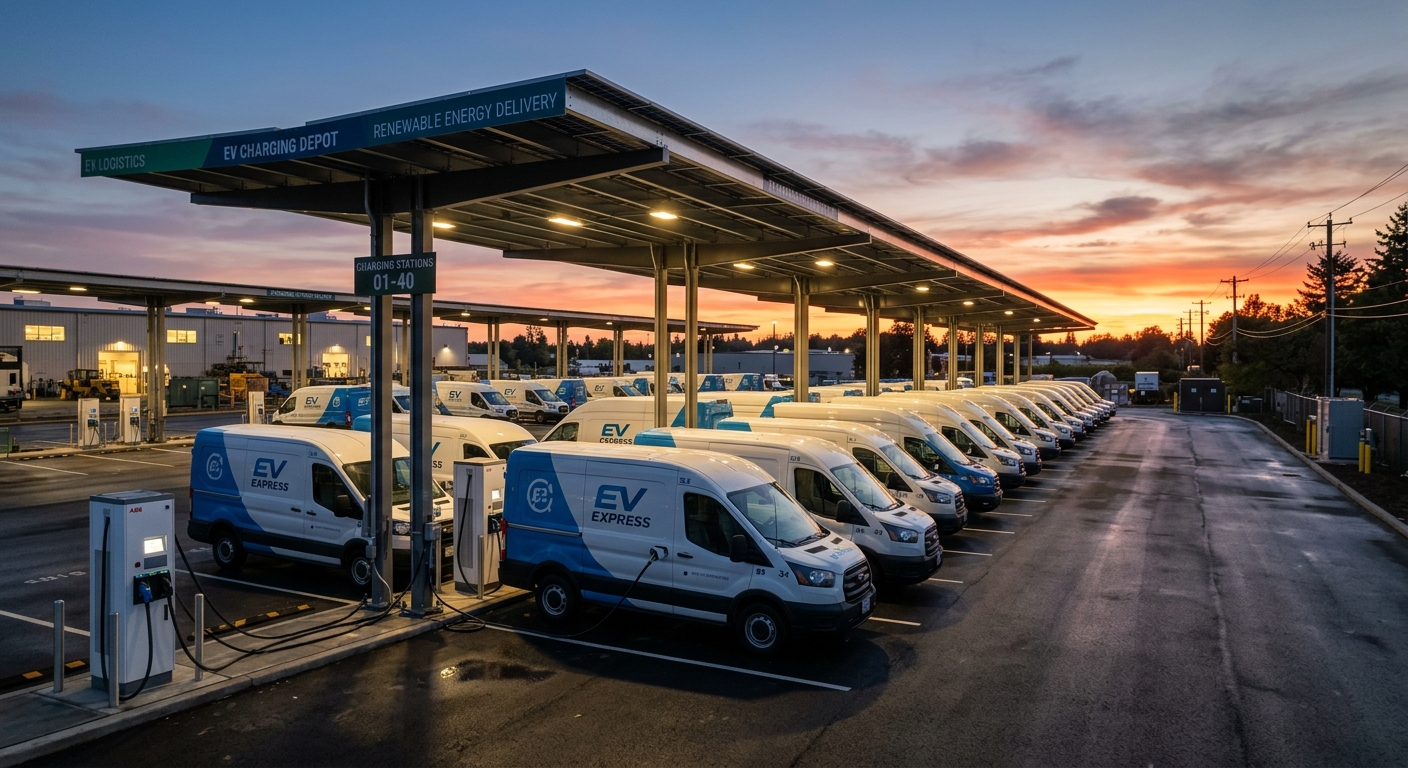
Electric delivery vans charging at a depot during evening hours
A Real Sizing Scenario: Retail Charging Hub with Midday Peak
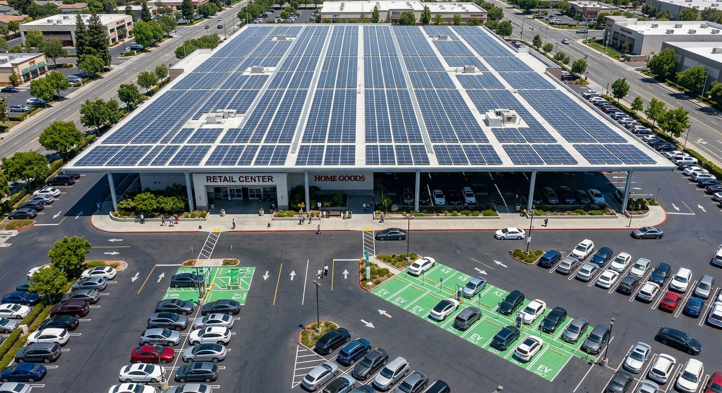
Consider a shopping center installing four 60 kW DC chargers with a 250 kW rooftop PV array, aiming to offset a meaningful share of grid draw during business hours. Following the dwell-time logic from our retail charging sizing guide, actual simultaneous charging demand rarely exceeds 140 kW even at peak weekend traffic — because not every bay is occupied and not every vehicle charges at full rate simultaneously.
Sizing the inverter to the full 250 kW PV nameplate would mean paying for capacity that’s almost never used, since actual coincident demand tops out around 140-160 kW. Instead, a 180 kW inverter with a DC:AC ratio of roughly 1.4 captures nearly all usable production, clips only the rare over-peak moments, and costs meaningfully less than a 250 kW unit — often 25-30% less on the inverter line item alone.
Where the Savings Actually Go
That capital difference doesn’t just sit as savings. Reinvesting it into a modest battery buffer smooths out the mismatch between solar peak (solar noon) and charging peak (afternoon pickup traffic), which does more for the site’s real-world grid offset than a bigger inverter ever would.
Rooftop solar array above retail parking lot with EV charging stalls
Battery Buffering Changes the Sizing Math Entirely
Adding a buffer battery between the PV system and the chargers doesn’t just smooth output — it fundamentally changes how small your inverter can be. Instead of sizing for instantaneous coincident peak, you size for average throughput and let the battery absorb the spikes.
This is the same logic explored in our piece on battery-buffered DC fast chargers versus grid upgrades, and it applies just as directly to solar sizing. A site with a 200 kW charging peak but only 80 kW of average sustained demand can run on a 100 kW inverter paired with a battery sized to cover the peak-to-average gap — instead of a 200 kW inverter sitting idle most of the day.
The trade-off is battery cost and cycling life, so this only pencils out where peak-to-average ratios are high — think retail and fleet-mixed-use sites, not steady industrial charging loads.
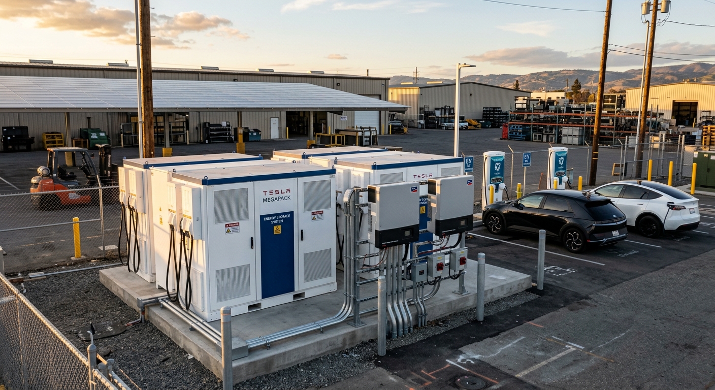
Battery energy storage cabinets beside solar inverters at EV charging site
Don’t Forget Dynamic Power Sharing Across Multiple Chargers
If your site has more than one charger drawing from the same PV-coupled system, static sizing assumptions fall apart fast. Real sites need dynamic allocation, not fixed per-charger caps.
The same dynamic power sharing principles covered in our load balancing and power sharing guide apply directly here — except now the available power pool fluctuates with cloud cover, not just grid capacity. A well-designed energy management system needs to shift allocation between chargers in real time as solar output drops, without tripping breakers or stalling active charging sessions.
Skip this layer and you’ll either oversize every downstream component to handle worst-case solar dropout, or you’ll get nuisance faults every time a cloud passes overhead. Neither is acceptable at a commercial site.
Common Oversizing Traps to Avoid
Sizing to nameplate PV capacity instead of realistic production. Use derated production figures — typically 75-85% of nameplate at peak — not spec sheet numbers.
Ignoring load coincidence. A large solar array producing power when nobody’s charging doesn’t reduce your inverter sizing needs one bit.
Skipping clipping loss analysis. A DC:AC ratio of 1.3-1.4 typically clips only 2-4% of annual production — a fair trade for a significantly smaller inverter.
Treating battery buffering as optional. On mixed-use or high-peak sites, skipping the buffer often forces an inverter 40-50% larger than necessary.
Designing for AC-coupling by default. If you’re building new infrastructure rather than retrofitting, DC-coupling’s efficiency gain compounds significantly over a 10-15 year system life.
A Practical Sizing Checklist
Before finalizing an inverter spec for a PV-coupled EV charging site, run through this sequence:
Pull actual (or projected) charging load curves by hour, not just charger nameplate capacity
Calculate coincident peak demand — the realistic maximum simultaneous draw, not sum of all charger ratings
Determine solar-load overlap: does generation coincide with charging demand, or are they offset?
Choose AC- or DC-coupling based on retrofit constraints versus long-term efficiency goals
Set DC:AC ratio between 1.2-1.4 based on site irradiance data and acceptable clipping loss
Evaluate whether a battery buffer reduces required inverter size enough to offset its added cost
This sequence consistently produces inverters 20-35% smaller than nameplate-matched designs, without sacrificing usable output.
Subscribe the newsletter to get updated to news and promotions
Cookies give you a personalized experience,Сookie files help us to enhance your experience using our website, simplify navigation, keep our website safe and assist in our marketing efforts. By clicking "Accept", you agree to the storing of cookies on your device for these purposes. Click "Adjust" to adjust your cookie preferences.For more information, review our Cookie Policy