Inside a 360 kW DC Charger: The Power Module Architecture That Determines Reliability
Home / Blog / Guidelines / Inside a 360 kW DC Charger: The Power Module Architecture That Determines Reliability
29 May, 2026
DC fast charger architecture
modular DC charger design
SiC power module EV charger
The reliability of a 360 kW DC fast charger isn’t determined by its enclosure or marketing spec sheet — it’s determined by how the power modules inside are wired, cooled, and controlled. A modular architecture using 20–40 kW SiC-based power modules with hot-swap capability, N-1 redundancy, and intelligent power pooling consistently outperforms centralized designs in field uptime, often by a factor of three or more. Everything else — connectors, HMI, payment — can be replaced in an afternoon. The power stack is what either earns the charger its keep or makes it a recurring service ticket.
Why the Power Module Is the Real Product
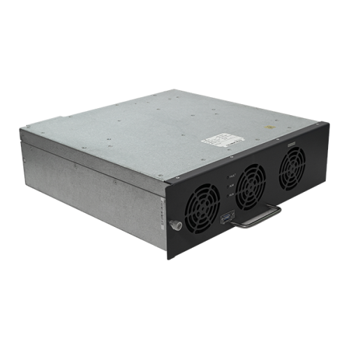
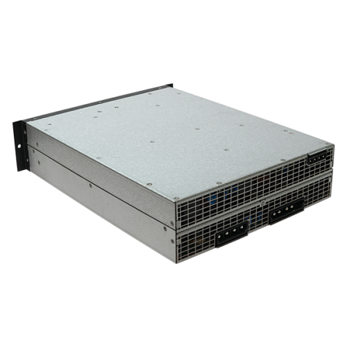
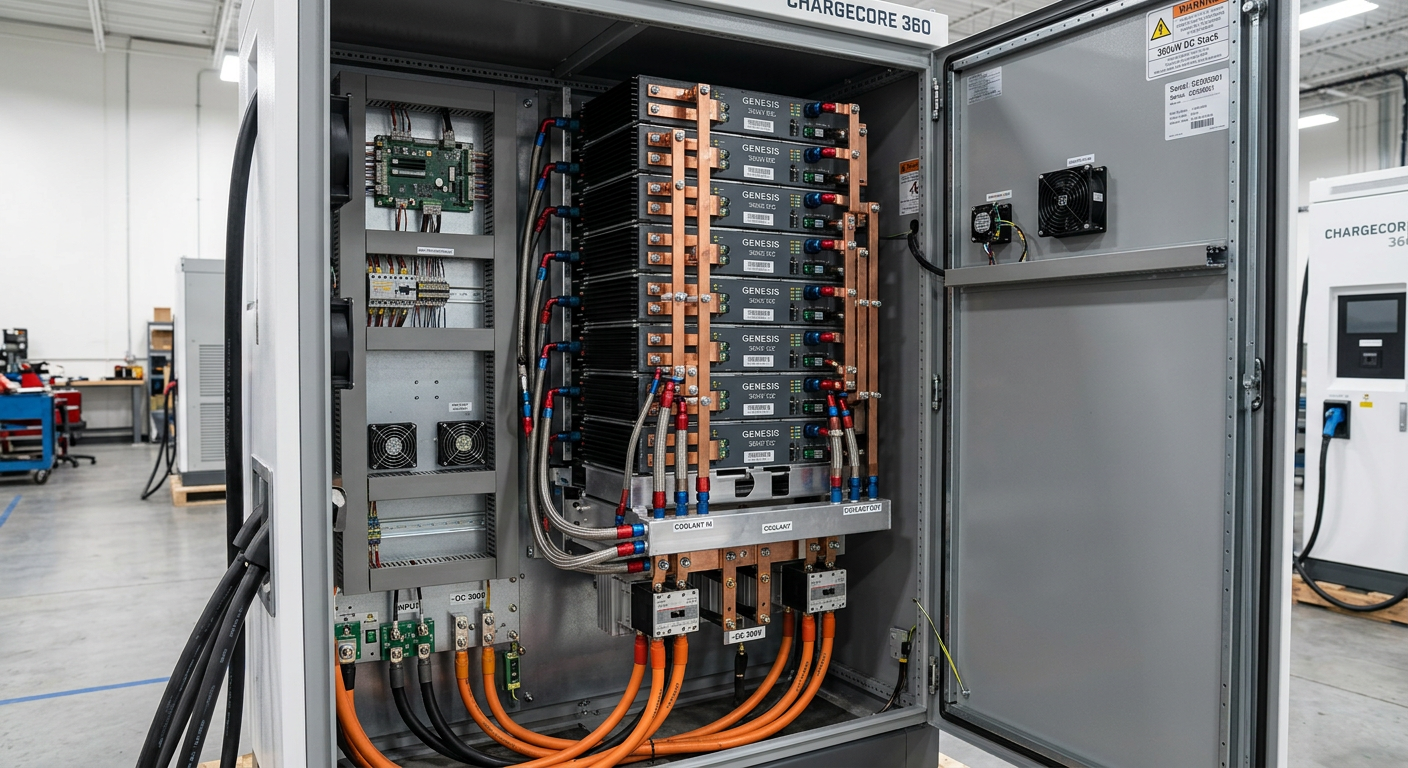
Walk past the touchscreen and the CCS2 holster, and the actual machine you bought is a stack of power modules. In a 360 kW unit, that’s typically twelve 30 kW modules, or nine 40 kW modules, working in parallel. Each one is a self-contained AC-to-DC converter with its own PFC front-end, isolated DC-DC stage, control board, and cooling loop.
Here’s the uncomfortable truth: two chargers with identical 360 kW nameplates can have wildly different lifetime costs. One might run 98% uptime for five years. The other will start derating in month eighteen, lose a module by month thirty, and become a parts-cannibalization project by year four. The difference isn’t the badge — it’s whether the module was designed for 100,000 hours of switching duty or 30,000.
If you’re sourcing chargers for a commercial EV charging station deployment, this is the question that matters most. Ask vendors for the module MTBF, the semiconductor brand, and the rated junction temperature margin. Anyone who can’t answer all three on the spot is not the supplier you want.
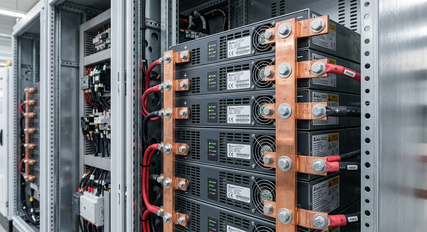
Close-up of stacked DC charger power modules with copper busbars
Modular vs. Centralized: Why Architecture Wins on Uptime
A centralized 360 kW design uses one or two large converter stacks. When something fails — a capacitor bank, a driver board, a single IGBT — the whole charger goes dark. Mean time to repair often runs eight hours or more because you’re waiting for a specialized technician with the right spare.
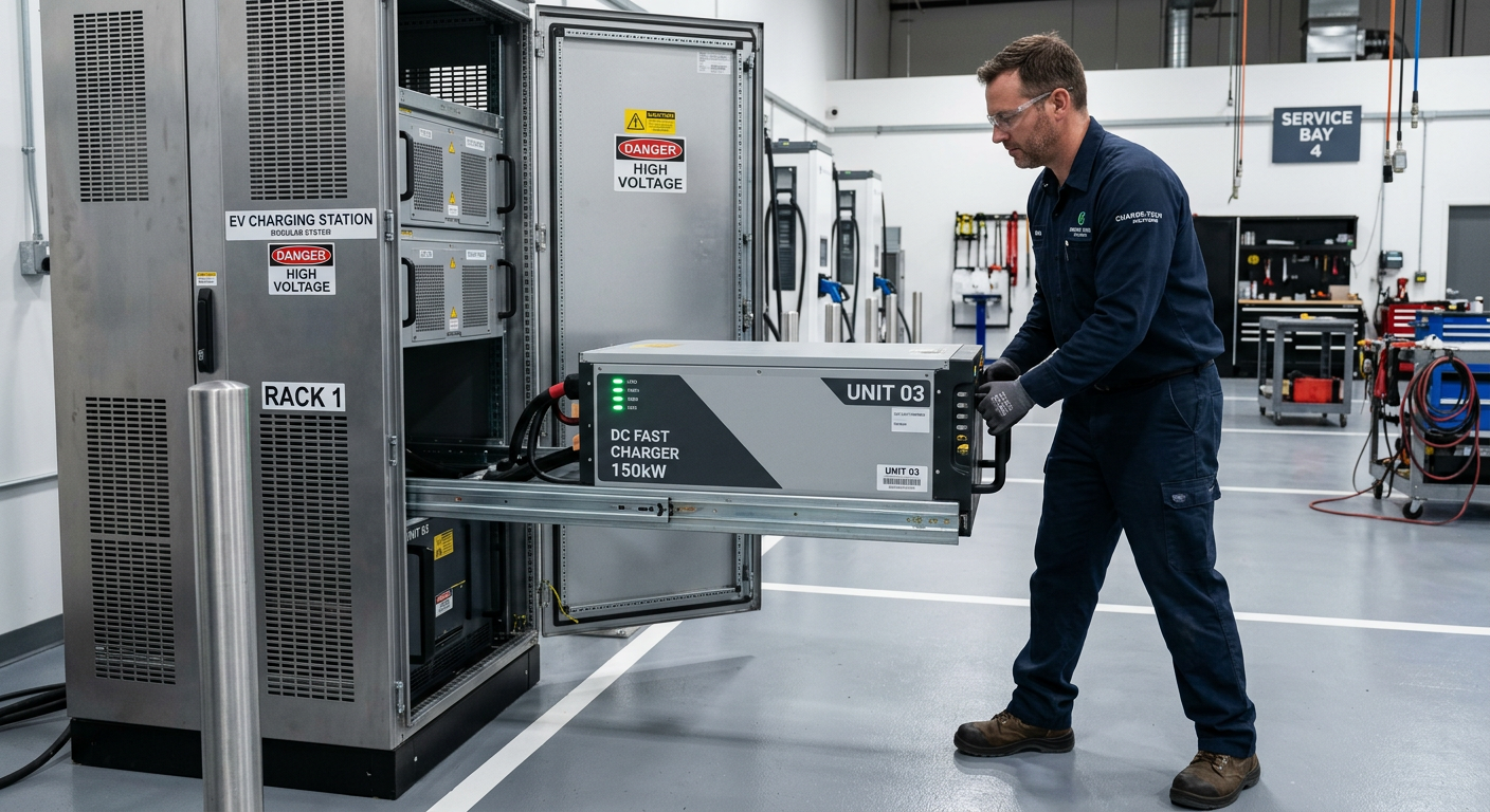
A modular architecture spreads the load across many smaller converters. Lose one 30 kW module out of twelve, and the charger keeps delivering 330 kW. The fault is logged, the operator dispatches a technician, and the module is hot-swapped in under twenty minutes — often without taking the station offline. That’s N-1 redundancy in practice.
What a real fault sequence looks like
For example, a highway corridor operator running eight 360 kW stations reported that across 18 months, they had 23 individual module failures. With modular hot-swap, total customer-facing downtime was under 11 hours. A centralized fleet of the same size would have racked up roughly 180 hours of full-station outage on the same failure rate.
SiC MOSFETs: The Component That Changed Everything
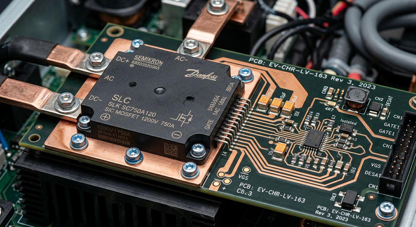
Silicon carbide MOSFETs are the single biggest reason a modern 360 kW charger can be smaller, cooler, and more efficient than a 150 kW unit from five years ago. SiC switches at 50–100 kHz with switching losses roughly a third of comparable IGBT designs. That translates to three things buyers actually care about:
Higher peak efficiency: 96–97% at full load versus 93–94% for IGBT-based modules.
Better part-load efficiency: Still above 94% at 25% load, where most public chargers actually spend their time.
Smaller magnetics and heatsinks: Higher switching frequency shrinks transformers and inductors, which is why a modern 40 kW module fits in a 4U chassis.
The catch: SiC devices are unforgiving of transient overvoltage and gate-driver design errors. A module designed around cheap Chinese-tier SiC dies with marginal gate-drive isolation will fail in the field — usually under high humidity or after a grid surge. Reputable manufacturers spec parts from Wolfspeed, Infineon, ROHM, or onsemi, and they design 20% derating margin on V_DS and junction temperature.
Silicon carbide MOSFET power module on a printed circuit board
Power Pooling: Stop Wasting Half Your Capacity
Static power allocation is the silent killer of charger economics. A 360 kW charger with two dispensers, each hard-wired to 180 kW, will deliver 180 kW to a single car even when the second port sits idle. That’s lost revenue every minute.
Power-pool architecture changes the rules. The modules sit in a shared bus, and a power-management controller dynamically dispatches available capacity to whichever dispenser is in use. One car plugged in? It gets the full 360 kW (up to vehicle limit). Two cars at different SoC? The controller allocates based on each vehicle’s accepted current, often giving 240 kW to the low-SoC vehicle and 120 kW to the one nearly full.
This is the same principle behind smart scalable EV charging infrastructure for fleets — treat power as a shared resource, not a fixed pipe. For high-throughput sites like delivery hubs and highway plazas, power pooling typically improves session throughput by 25–40% with zero added hardware.
Cooling Strategy: The Difference Between 8,000 and 80,000 Hours
Heat is what kills semiconductors. Every 10 °C reduction in junction temperature roughly doubles the lifetime of an SiC device. So how the module is cooled matters as much as what’s inside it.
Forced air vs. liquid cooling
Forced-air modules use high-static-pressure fans pushing filtered air through a finned heatsink. Cheap, simple, and adequate for indoor or temperate environments — but the fans themselves become the weakest link. Bearing failure typically shows up at 40,000–60,000 operating hours. In a 24/7 highway environment, that’s five to seven years.
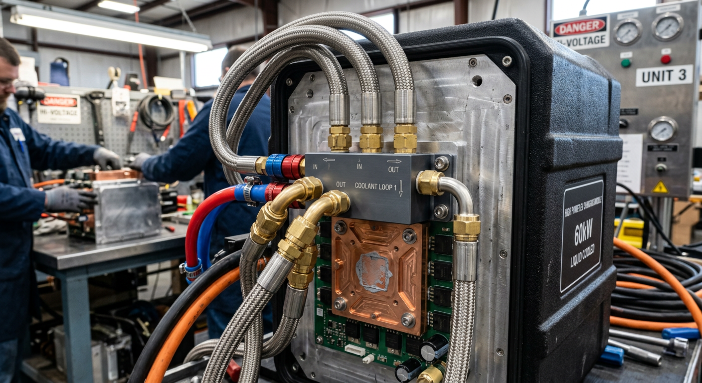
Liquid-cooled modules pipe a glycol-water mix through cold plates bonded to the SiC packages. Junction temperatures stay 15–25 °C lower, intake air filters are eliminated, and acoustic noise drops dramatically. The trade-off is plumbing complexity and pump reliability — but in summer climates above 35 °C ambient, liquid cooling is the only way to avoid thermal derating at the worst possible time: peak demand on the hottest afternoon.
For 360 kW class units deployed in the Middle East, southern Europe, or the U.S. Sun Belt, liquid-cooled modules aren’t a luxury — they’re the only architecture that holds nameplate output through a full summer.
Liquid cooling cold plate assembly on a DC charger power module
Communication: Where Reliability Quietly Falls Apart
You can have perfect SiC, perfect cooling, and perfect redundancy — and still have a charger that fails 8% of sessions because the CAN bus between modules and the master controller throws errors under EMI load.
Inside a well-engineered 360 kW unit, you’ll find three distinct communication layers:
Internal module CAN/CANopen bus: coordinates output current sharing, fault reporting, and load balancing between modules. Isolated transceivers and proper shielding are non-negotiable.
Vehicle communication (PLC/HomePlug GreenPHY): handles CCS handshake, ISO 15118 Plug & Charge if supported, and current request loops.
Most field communication errors trace back to either grounding loops or EMC bleed from the high-frequency switching stage into the low-voltage signal lines. Manufacturers who treat EMC as an afterthought ship products that pass certification on the bench and fail in the field. This is closely related to how BMS CAN communication shapes charging behavior on the vehicle side — both ends of the link have to be robust.
Serviceability: The Spec Sheet Number Nobody Prints
Here’s a number you won’t see in any vendor brochure: Mean Time To Repair (MTTR). It’s the single best predictor of total cost of ownership for a high-power charger.
Well-designed modular chargers achieve 15–30 minute MTTR for a power module swap. Bad designs require disassembling the front bezel, disconnecting liquid cooling lines, dropping busbars, and recalibrating module addresses — turning what should be a quick swap into a four-hour job.
Things to verify before purchase:
Modules slide out on rails with blind-mate DC and signal connectors (not bolt-up busbars).
Coolant connections are dry-break quick-disconnects, not threaded fittings.
Module addressing is automatic via bus position, not DIP-switch configured.
Front access only — you do not want a charger that requires rear clearance, because most installations don’t have it.
One fleet operator we worked with switched their second deployment from a bolt-up design to a rail-mount modular design and cut their annual service hours per charger from 38 to 9. Same uptime target — a quarter of the labor.
Technician hot-swapping a modular power unit in a DC fast charger
What to Ask Your Manufacturer Before You Sign the PO
If you’re buying — or specifying — 360 kW chargers for a project, here’s the short list of questions that separate serious suppliers from spec-sheet warriors:
What is the rated MTBF of the power module, and at what ambient temperature?
What SiC device brand and part number is used? What’s the V_DS derating?
Is the module hot-swappable under load, or only with the system de-energized?
What’s the efficiency curve from 10% to 100% load — not just the peak number?
What’s the IP rating of the module itself (not just the enclosure)?
How is current sharing between modules controlled — droop, master-slave, or active digital?
What’s the documented MTTR for a module swap, including coolant handling?
If you get vague answers or marketing-speak, that’s your signal. The good manufacturers will pull out a block diagram and walk you through it.
Building the Right 360 kW Solution for Your Site
The takeaway is simple: a 360 kW DC charger lives or dies by what’s inside the power cabinet, not what’s printed on the front. Modular architecture, SiC devices with real derating, intelligent power pooling, appropriate cooling for the climate, and ruthless attention to serviceability — those five factors determine whether your charger is an asset or a liability.
At evaisun, we design our high-power DC platforms around hot-swappable SiC modules with liquid cooling options for high-ambient deployments, OCPP 2.0.1 native support, and a service architecture built for 15-minute module swaps in the field. If you’re scoping a project — fleet depot, highway corridor, or destination charging — we’re happy to share block diagrams, efficiency curves, and reference deployments. Reach out through our OEM and ODM services page, or browse more technical write-ups on the evaisun blog to keep digging.
Subscribe the newsletter to get updated to news and promotions
Cookies give you a personalized experience,Сookie files help us to enhance your experience using our website, simplify navigation, keep our website safe and assist in our marketing efforts. By clicking "Accept", you agree to the storing of cookies on your device for these purposes. Click "Adjust" to adjust your cookie preferences.For more information, review our Cookie Policy