EV Charger Commissioning: The Checks That Catch Problems Before Handover
Home / Blog / Guidelines / EV Charger Commissioning: The Checks That Catch Problems Before Handover
10 Nov, 2026
charger handover documentation
DC fast charger commissioning
EV charger commissioning checklist
EV charger site acceptance testing
Charger faults rarely announce themselves on handover day. A latent defect in a lug torque, a gland seal or a protection setting sits quietly through a five-minute plug-in demo, then surfaces weeks later under full load, in rain, or when the network link drops mid-session. That is why a proper commissioning run tests the unit under load and under deliberate fault, and records the readings before anyone signs.
Key takeaways
Split commissioning into three separately signed layers: the electrical installation, the charger as a machine, and the charger as a network node. Each fails in its own way and each belongs to a different party.
A plug-in demo with a vehicle proves a handshake, not capacity. Rated output and thermal behaviour only appear under a staged load bank held until the cabinet reaches thermal steady state.
Insulation monitoring that has never been tripped is a claim. Introduce a known fault during commissioning and confirm the response before anyone signs.
Compare the energy reported to the platform against a reference meter at a known load; small drift on a busy site is a permanent, invisible revenue leak.
Rehearse mains loss, emergency stop, residual current trip and network loss while someone is watching, and record what normal looks like so the first real fault can be diagnosed against it.
A Charger That Powers Up Is Not a Commissioned Charger
Commissioning is three separate jobs wearing one name. Split them, give each one its own pass criteria and its own signature, and the gaps close on their own.
The electrical installation
Feed sizing, earthing and bonding, protection device selection and discrimination, cable routing and mechanical protection. The electrical contractor owns this layer, and it is the only layer that can seriously injure someone if it is wrong.
The charger as a machine
Isolation, pre-charge and contactor behaviour, output voltage and current accuracy, thermal behaviour at rated load, and the protective functions the unit shipped with. This belongs to the charger supplier, and on many sites it is never tested beyond whatever the display happens to show.
The charger as a network node
Connectivity, heartbeat stability, transaction handling, authorization, metering and firmware configuration. The network operator or CPO integration team owns it, which in practice often means nobody on site does.
The faults that survive a plug-in demo are specific:
A terminal torqued to half specification that runs cool at low current and heats up once real load arrives.
A protective earth bond that only matters on the day fault current needs a path.
An insulation monitoring function that shipped disabled because a previous site complained about nuisance trips.
A heartbeat that stops after the first hour, long after the installer has packed up.
Write the pass criteria and the record sheet before the units arrive. On handover day the pressure runs one way: accept whatever the screen shows so the site can open. A pre-agreed sheet with numbers on it is the only thing that survives that pressure.
Then sequence the work: dead checks with the supply isolated, energize without load, load test to thermal steady state, network and metering acceptance, and finally fault rehearsal. Jumping to a load test with an unproven earth is how commissioning injuries happen.
Dead Checks: What to Verify Before the First Energization
These checks cost an hour and prevent the expensive category of fault, the kind that hides until the site is busy. All of them happen with the supply isolated.
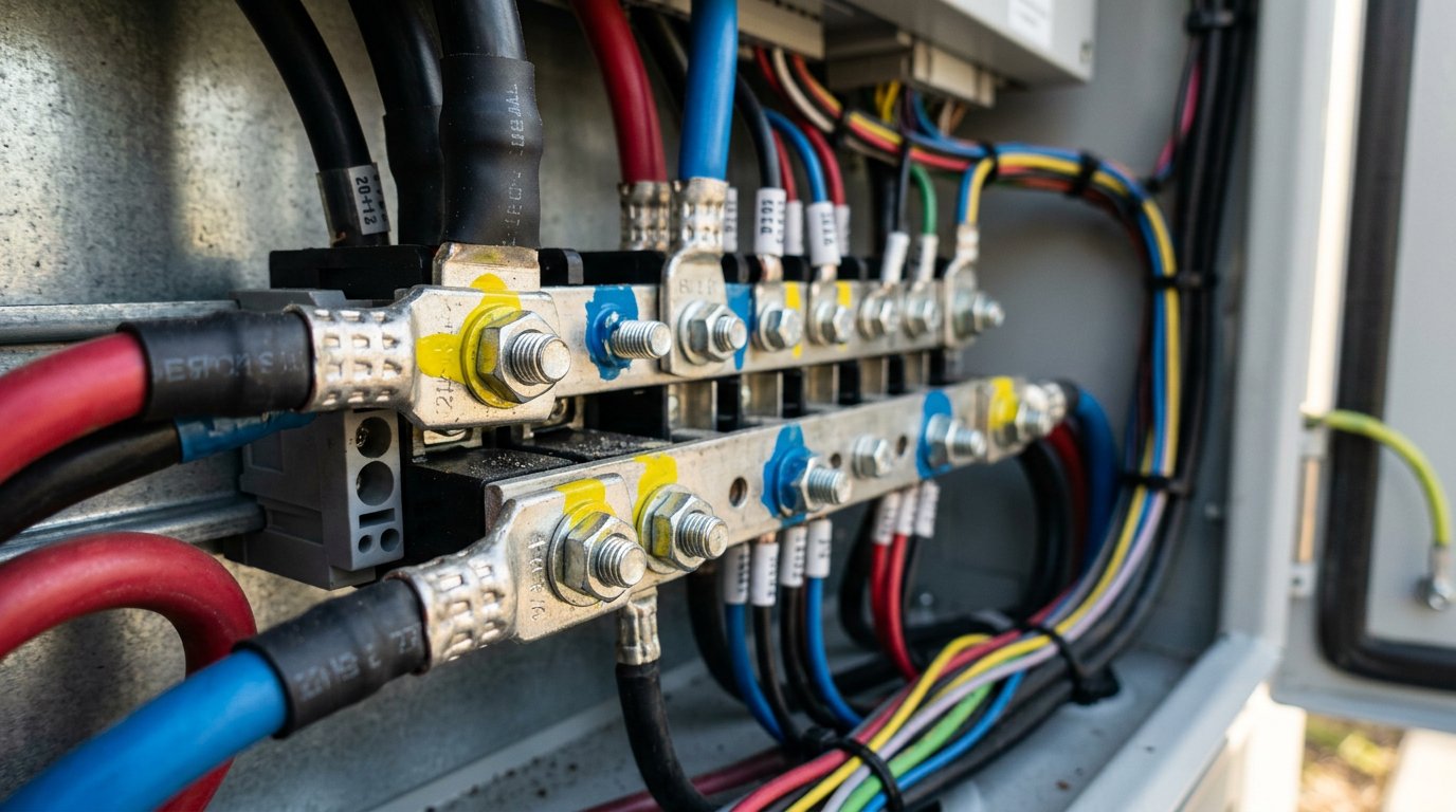
Torque every terminal to the manufacturer specification with a calibrated wrench, mark each fastener, and photograph the marks. An under-torqued lug is invisible at light current and expensive at rated current on a hot afternoon.
Prove protective earth continuity from the charger frame to the earth bar, and confirm the earth bar goes to earth rather than to a neutral bond.
Check gland orientation and drip loops. A gland entering the top of an enclosure without a loop lets water track down the jacket into the terminal compartment. That one surfaces after the first wet winter, not on handover day.
Respect the airflow envelope. evaisun’s forklift battery charger installation guide calls for at least 0.5 meters of clearance around the charger, and the same logic applies to any air-cooled cabinet. A wall or a stack of pallets in the intake path turns a rated unit into a derated one.
Mount it level and upright. That same guide states the charger must sit horizontally and never upside down or on an incline. A tilted installation stresses the module rack and lets condensate pool at the low end of the enclosure.
Record the ambient temperature on the day. The installation guide specifies an environment of -20°C to 45°C, so a unit commissioned on a 38°C afternoon starts its service life far closer to its thermal ceiling than one commissioned in spring.
Keep power and signal cabling on separate routes with a defined separation distance. Noise induced onto a communication pair produces intermittent faults that get blamed on firmware for months.
Torque-marked cable lugs inside an EV charger terminal compartment
Earthing, Bonding and Insulation Resistance: The Checks a Socket Tester Cannot Do
A socket tester tells you there is a live, a neutral and an earth. It does not tell you the earth will carry fault current, and it does not tell you the feed is sound before you bolt electronics onto it. Those are two separate measurements, and both need a number written down.
Prove the fault-current path
Measure earth loop impedance with a proper instrument, or run a protective earth continuity test from the charger frame to the earth bar and from the earth bar to the installation earth. Record the reading. One measurement on a dry day is a data point, not a certificate: it confirms the path existed at that moment, at that soil moisture and that temperature.
Insulation resistance, in the right order
Test the feed before the charger is connected, at the correct test voltage, with surge protective devices and the unit itself isolated. Testing with the electronics attached can damage arresters and input stages, and a wounded input stage frequently survives right up to the first full-load run, which is exactly when nobody is still thinking about commissioning.
Residual current protection is not a formality
Match the device to what the unit actually requires. A Type A device will not detect a smooth DC residual current, which is why some chargers call for a Type B device or an integrated DC detection function. Confirm which one this site has before you energize it, not after a trip.
Then confirm the charger’s own protective functions are enabled rather than bypassed. If you find insulation monitoring disabled, stop and write down what you found: which function was off, the setting as found against the factory default, who is responsible for it, and what has to be verified at this site before it is switched back on. An undocumented disabled function will be discovered by somebody else, months later, with no paper trail pointing back to the day it was turned off.
Treat the requirement for a properly grounded socket as the floor rather than the target. evaisun’s guide requires connection to a properly grounded electrical socket, and a commercial installation with a separately derived earth needs that continuity proven end to end, not inferred from a green lamp.
Baseline Power Quality: Measure the Site Before You Blame the Unit
When a charger misbehaves in month eight, the argument is always the same: the site says the unit, the supplier says the supply. A baseline captured on handover day ends that argument before it starts, because both parties signed the same numbers.
Record per-phase voltage, frequency, phase imbalance and voltage THD with the charger off, then again at full load. The gap between the two snapshots describes how stiff the supply really is at this address.
Log for a full working day where the site has other large loads switching. A compressor or a welder starting next door is invisible in a ten-minute spot check and unmissable in the charger’s error log three months later.
Get the site electrician to sign the baseline on the same sheet as the charger test results. A number recorded jointly is hard to dispute later, and a number recorded only by the installer is easy to dismiss.
Note the neutral conductor condition and whether anything else shares it. A degrading neutral shows up as voltage wandering between phases as load changes, and it will be blamed on the charger every time.
Capture the no-load snapshot before the charger is connected at all, so you can separate what the site brought from what the charger adds.
Keep the instrument model and serial number on the sheet. If a dispute ever reaches a third party, the credibility of the measurement rests on the instrument as much as the reading.
The Load Test: How to Prove Rated Output When the Vehicle Is the Limiter
A vehicle’s battery management system decides how much current it will accept. A car that takes a fraction of the cabinet’s rating proves nothing about whether the cabinet holds its own rating. A plug-in test is a compatibility check, and calling it a capacity test is how underperforming sites get signed off.
Use a resistive or electronic load bank sized to the unit. If none is available, book one before the first month of operation ends rather than accepting a vehicle test as a substitute.
Step the load up in stages at roughly a quarter, half, three quarters and full rating. A protection trip or a voltage sag can then be tied to a specific point instead of appearing as an anonymous failure.
Hold at full load until thermal steady state. Ramp-up behaviour is not steady-state behaviour, and the first derate usually arrives after the cabinet has soaked, not during the first minute.
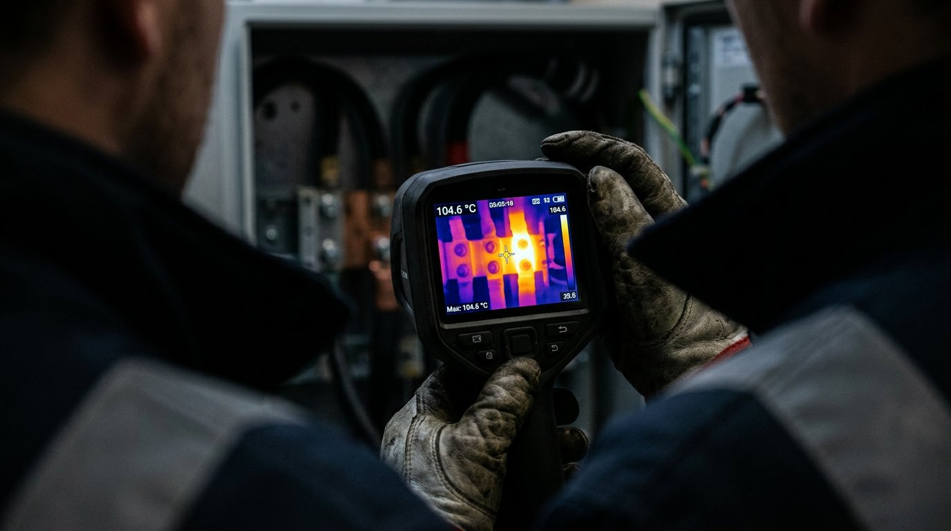
Thermal image the input terminals, output busbars, contactor bodies and module exhaust at every stage. One terminal running noticeably hotter than its neighbours is a loose connection you just got the chance to fix for free.
Compare achieved output against the datasheet rating and the derating curve for the ambient temperature on the day. Knowing how to read a DC charger datasheet matters here, because the headline figure and the usable figure are rarely the same number.
On modular units, compare per-module currents. Uneven sharing means one module carries the site and ages first while the others sit idle, and the failure lands on whoever holds the warranty.
Take a depot that commissions in April and runs its first hot week in July. A unit that reached full rating on a mild afternoon has been tested, but not tested at the ambient it will actually see, and the test sheet should say which ambient was used so nobody has to guess later.
Thermal camera showing hot busbar terminals in a charger under full load
DC-Side Checks: Insulation Monitoring, Contactor Behaviour and Connector Safety
The output side is where a charger can hurt somebody who is simply trying to plug in a car. Every check below answers one question: does the unit ever present voltage where it should not, and does it ever let a connector go under load?
Insulation monitoring has to be seen working
Verify the function is active and that it actually reports a fault. Introduce a known fault following the manufacturer’s procedure, confirm the response, then clear it and confirm the unit returns to service. Skip the injection and you finish the day with no evidence the function responds to anything at all.
Contactor weld detection
A unit should detect a stuck output contactor and refuse to close, rather than closing onto a live DC bus. Confirm the detection works rather than assuming the logic exists.
Measure the pins, do not read the screen
With no session active, measure the connector pins and confirm the output is de-energized. A display reading stopped is not the same as a dead bus. Then exercise the connector lock actuator and the interlock that blocks unplugging under load: a lock that fails to engage is an arcing risk and a warranty claim waiting for a customer to yank the handle.
Where connector temperature sensing is fitted, confirm the sensor reads ambient before the first session. A dead sensor reports a cool connector, which disables the derating meant to protect it. On AC units, verify control pilot and proximity pilot behaviour with the vehicles actually expected on site, including the case of a cable connected but not latched.
Network and Metering Acceptance: Proving the Back Office Can Run the Site
A charger that charges is not yet a managed asset. These tests decide whether the operator can bill, control and diagnose the site without sending someone to stand in front of it.
Confirm a stable connection to the platform. Initial connect, then a heartbeat sustained for an hour rather than a minute, then a clean reconnection after a deliberate network drop. A link that survives a minute and dies at sixty-five is the classic failure, and recurring communication errors usually trace back to cabling, configuration or an unstable backhaul rather than the charger firmware.
Install and verify the TLS certificate, and confirm the unit rejects an unauthorized connection attempt where the platform supports that test. These belong with the wider cybersecurity checks for networked chargers, not in the optional extras column.
Start and stop a session remotely, and confirm the transaction closes cleanly with the correct stop reason attached.
Compare reported meter values against a reference meter or a calibrated check at a known load. A small percentage of drift is the difference between a profitable site and one the owner quietly subsidises for years.
Test offline authorization. With the link down, does a known card still start a session, and does that session reconcile once the connection returns?
Push a power limit or smart charging profile and confirm the unit actually reduces output instead of acknowledging the command and ignoring it.
Record firmware version, OCPP configuration keys and meter serial number per unit. When a unit misbehaves in eight months, this sheet is where the comparison starts.
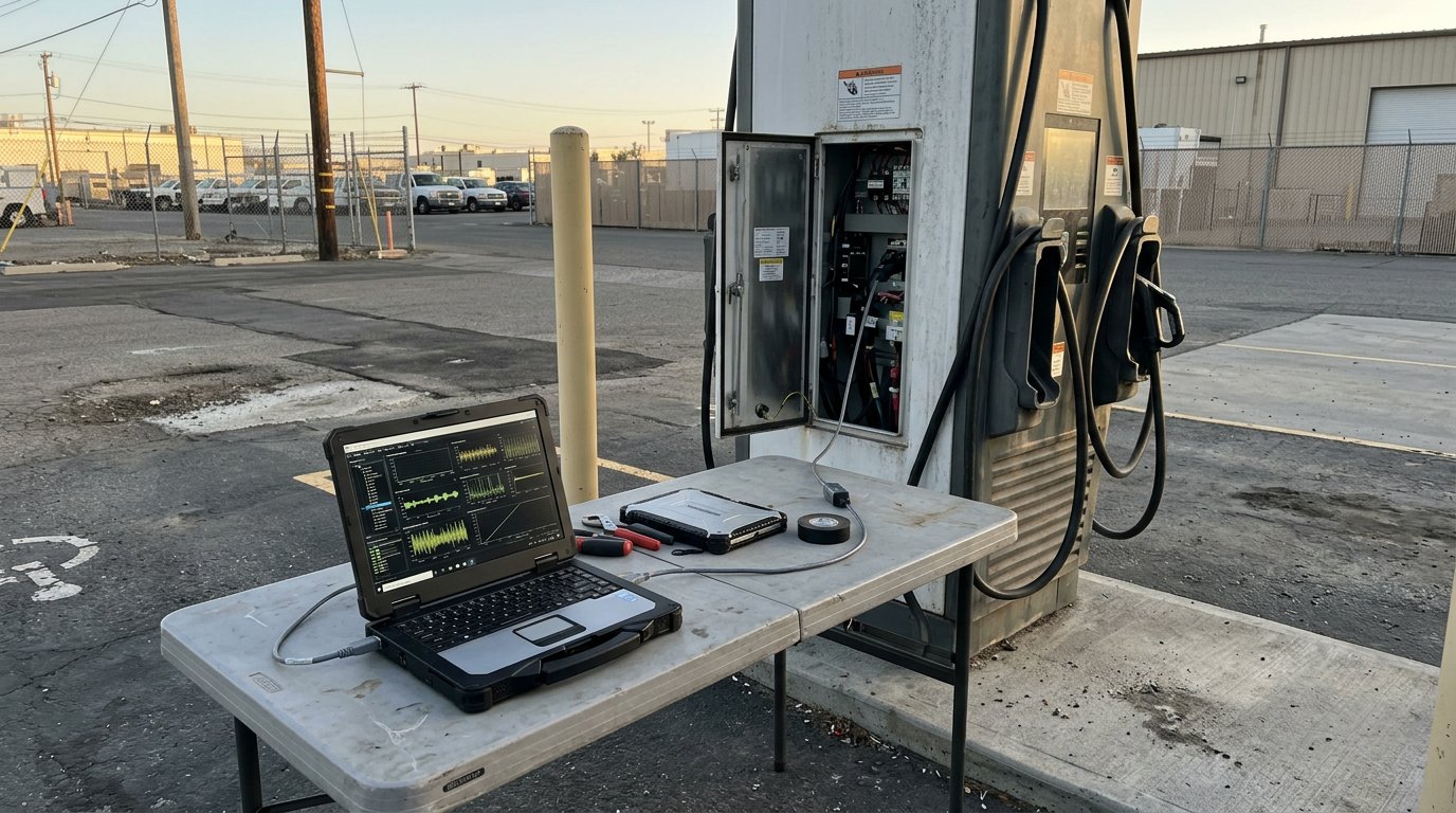
Laptop connected to a charger service port showing network status graphs
Fault Rehearsals: Trip It on Purpose While Someone Is Watching
Every scenario below will happen in service. The only decision is whether it happens first with a witness and a record sheet, or first with a customer and a support ticket.
Scenario
What must happen
What to record
Mains loss and restore
Output de-energized, orderly shutdown, defined restart behaviour
Pin voltage, restart time, event in the platform log
Emergency stop pressed and reset
Contactors open, no restart until reset, clear local indication
Pin voltage after trip, reset procedure, who performed it
Residual current trip
Output isolated, fault latched and announced
Device type, trip indicator, recovery steps
Network loss mid-session
Session continues per local policy, transaction stored for later upload
Session state, reconciliation after reconnect
Enclosure opened while energized
Interlock or tamper detection responds as designed
Local alarm, platform notification, output state
Connector lock failure
No session start, or orderly stop, never a live release
Pin voltage, lock feedback, error code
Over-temperature
Derate first, then stop, with the reason logged
Derate threshold, ambient at test, recovery behaviour
Then confirm auto-restart behaviour matches site policy: an unattended depot usually wants automatic recovery from a mains dip, while a public site may want a manual reset with an error code so a genuine fault is not silently cleared. For each scenario, start a stopwatch at the moment of the trip and log two things: how long the unit took to come back, and the path it took back, whether it restarted on its own, waited for a reset, or returned in a restricted state. A unit that needs a technician to clear a short interruption costs the operator a morning of charging.
Record who witnessed each rehearsal and when. Before the witness sheet is signed, walk the table row by row and check that a reading, a name and a time sit against every scenario.
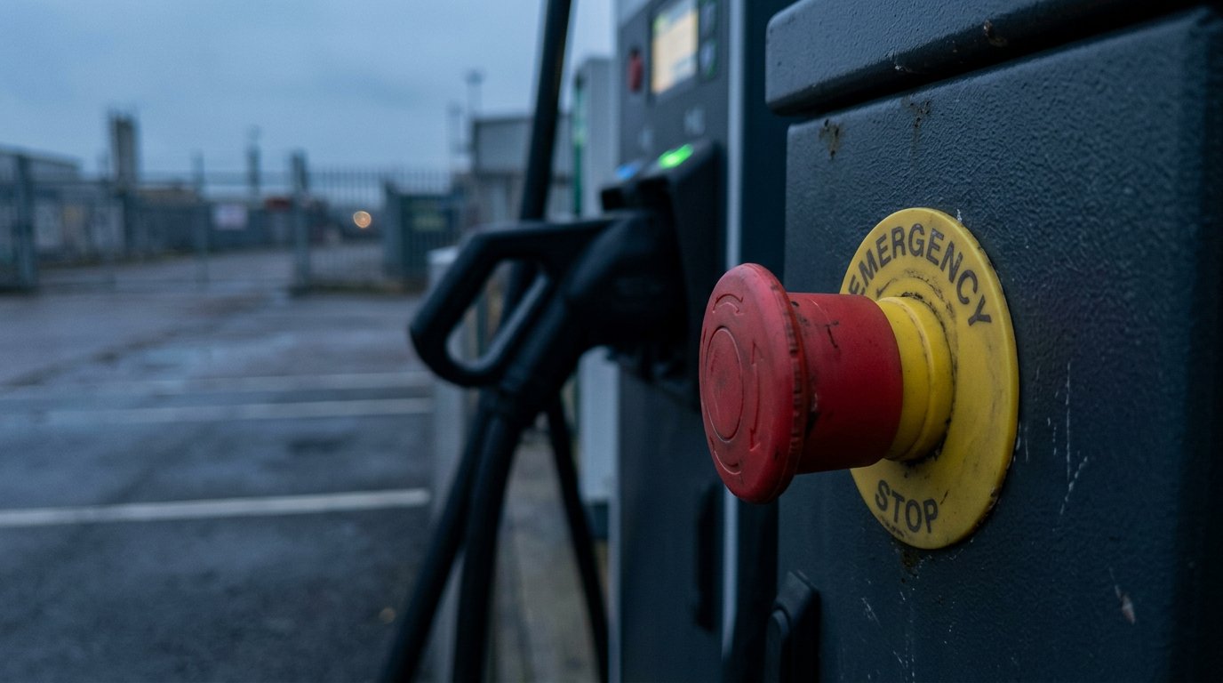
Emergency stop button pressed on a DC fast charger during testing
Sign-Off: What to Leave Behind, and What to Ask Your Supplier
Handover is an evidence handover. If time runs short on the day, spend what is left on five checks: protective earth continuity, a full-load thermal image of the terminals, insulation monitoring proven with a simulated fault, meter readings against a reference, and one complete fault rehearsal. Those five catch the faults that cost the most to find later.
Build a handover pack: as-built single-line diagram, torque and test logs with instrument details, insulation resistance and loop impedance readings, load test log and thermal images, firmware and OCPP configuration export, serial numbers, a signed witness sheet with names and date, and the warranty start date. Warranty disputes are liability questions in disguise, and the liability side of charger ownership is settled with documents long before it reaches an insurer.
Train the site’s first-line responder on the stop procedure, the error codes worth reporting, and the escalation contact. A site that can describe a fault accurately saves a service visit.
Treat certification as a starting point. evaisun states its solutions carry UL and CE certifications, which tells a buyer the design was tested to a standard in a laboratory. It does not tell you whether the earth at this particular site is sound, which is why the site tests above still have to happen.
Ask your supplier what ships in the box and what comes on request: factory test reports per serial number, wiring and terminal diagrams, the self-test procedure, and the list of protection functions that must be enabled on site. Getting those documents up front removes a recurring back-and-forth step from every commissioning.
If you are planning a rollout and want the installation, protection and test documentation that goes with the hardware, talk to evaisun’s team before the first unit ships rather than after the first fault.
Frequently asked questions
How long should EV charger commissioning take?
The test sequence sets the duration, not the paperwork. Holding a load test to thermal steady state is usually the longest single step, because the cabinet has to soak before its real behaviour shows up. A site that finishes suspiciously fast has often skipped that hold. Budget the day around the load test and the fault rehearsals, not around the visual inspection.
Can a site be accepted without a load bank?
Only as a compatibility check, not a capacity test. Without a load bank you can still verify earthing, insulation monitoring, connector safety, network behaviour and metering against a reference, but you cannot prove rated output or thermal performance. If no load bank is available on handover day, book one before the first month of operation ends.
Does a factory test report replace site commissioning?
No. A factory report proves the unit met its specification on the day it was tested, on the manufacturer’s supply, with the manufacturer’s instruments. It says nothing about the earth at this site, the torque applied during this installation, or the network this unit must talk to. Use it as the reference value your site readings are compared against.
Subscribe the newsletter to get updated to news and promotions
Cookies give you a personalized experience,Сookie files help us to enhance your experience using our website, simplify navigation, keep our website safe and assist in our marketing efforts. By clicking "Accept", you agree to the storing of cookies on your device for these purposes. Click "Adjust" to adjust your cookie preferences.For more information, review our Cookie Policy