Megawatt Charging System (MCS): What Truck Fleets Should Specify Before It Scales
Home / Blog / Industry News / Megawatt Charging System (MCS): What Truck Fleets Should Specify Before It Scales
27 Oct, 2026
MCS charging for truck fleets
MCS vs CCS charging
megawatt truck charging specification
SAE J3271
The Megawatt Charging System is the CharIN-developed, SAE J3271 high-power DC charging system built for heavy-duty trucks, and the number that decides whether a bay actually works is delivered energy per stop, not peak kilowatts. Fleets that compare 1 MW nameplates while ignoring state-of-charge taper, ambient derating, site capacity and cable cooling buy the wrong hardware and inherit the wrong service contract. What follows is the arithmetic a tender document actually needs.
Key takeaways
MCS is a CharIN-developed system standardised as SAE J3271, covering inlet, connector, cable, communication and charger interface. Shipping hardware runs at roughly 1 to 1.2 MW and 1500 A continuous; the 3 to 4 MW figures you read elsewhere are a standard’s headroom, not a product rating.
Delivered kilowatt-hours decide dwell time, not peak kilowatts. Vehicle acceptance, state-of-charge taper and ambient derating can each cut a session well below the nameplate, so demand a kWh-versus-time curve at a declared pack size, starting state of charge and ambient temperature.
Size the bay from the route: energy per leg divided by the available break gives required average power, capped by what the vehicle will accept. A 500 km leg at 1.4 kWh per km needs about 700 kWh, which is roughly 930 kW average inside a 45-minute stop.
The long-lead item is the electrical service, not the charger. Run load calculation, utility interconnection study, transformer and switchgear selection, then civil works, then commissioning, in that order.
Score tenders on the derating curve and the session curve first, and treat the headline kilowatt number as a marketing column until both documents are on the table.
What the Megawatt Charging System Is, and What It Is Not
MCS is a CharIN initiative, standardised as SAE J3271, and the acronym covers far more than a plug. It spans the vehicle inlet, the connector, the cable assembly, the high-level communication layer and the interface to the charger cabinet. That scope matters the moment you write a tender, because asking for an MCS charger is shorthand for a whole system specification. A vendor who answers with a power figure has answered a different question. J3271 was written to meet the reliability expectations commercial vehicles carry. You will still find the line, common in 2021 commentary, that the MCS connector is set to become the worldwide standard charging connector for the Tesla Semi, the Freightliner Cascadia and other large commercial vehicles. Treat it as a forecast written before either truck had a production inlet to inspect. The eCascadia’s production inlet does not support it. Ask the OEM which inlet your tractor actually ships with before a connector type appears anywhere in the tender.
The envelope is defined around a 1250 V DC class with current headroom toward 3000 A. That headroom is what makes multi-megawatt figures physically achievable. Hardware you can order today sits near the 1 to 1.2 MW mark at 1500 A continuous, and one shipping product, the MCS1200, quotes exactly that: 1.2 MW at 1500 A continuous. Elsewhere you will read that the technology reaches up to 4 MW, or that it delivers up to 1 MW and pulls a session under an hour. Those are statements about different things. One is a product rating you can test against, one is a standard’s ceiling, one is a rounded summary. Know which you are putting in a document.
How MCS compares with the chargers you already run
Depot AC charging runs at 7 to 22 kW and suits a vehicle parked for a shift. CCS2 DC fast charging typically tops out around 500 kW. MCS sits above that, sized for the tractor unit on a corridor route rather than the van that comes home every night. If you need the wider mechanical map, our guide to EV charging connector types covers it. One trap to avoid: pantograph charging for buses is a separate standard solving a separate problem, so a fleet running both coaches and trucks should not assume one answer covers both.
Why you cannot simply scale a CCS charger up
The bottleneck sits in the contact interface and the cable’s thermal limit rather than in the power stack inside the cabinet. A 500 kW CCS connector fed by the same power modules cannot reach megawatt current without a different connector geometry and active cooling. Anyone offering megawatt throughput through a CCS-shaped connector is offering something worth inspecting closely.
Four words that are not the same claim
MCS-ready, MCS-capable, conformant and certified describe four different states of readiness. Ask which claim a vendor is making, then ask for the evidence behind it. A brochure sentence is not evidence. Write the revision into the specification as well: J3271 and its conformance ecosystem are still maturing, so name the revision you will be tested against, and check CharIN and SAE for the current published one rather than trusting any article, this one included.
The Gap Between Nameplate Power and Energy Actually Delivered
A charger rating is a capability. The result belongs to the vehicle. Connect a 1 MW charger to a truck whose battery management system accepts 500 kW and the session runs at 500 kW, and no amount of cabinet engineering changes that. Three mechanisms eat the difference between the nameplate and the kilowatt-hours that land in the pack.
Taper, ambient and partial load
State-of-charge taper. The pack takes current in a constant-current phase, then switches to constant-voltage as it fills, so the last portion of a charge takes disproportionately long. A bay designed to deliver a truck at 100 percent is paying for power it can never sell back. Design around an 80 percent departure window unless the duty cycle genuinely needs the last fifth of the pack.
Thermal derating. Sustained current is limited by the temperature its contacts and components can hold. A unit rated at 1500 A at 25 degrees Celsius will not hold 1500 A at 40 degrees. Demand the derating curve at your site’s design ambient temperature, not a single number pulled from a headline.
Partial-load efficiency. Most of a megawatt session runs below the top rate, because taper and the ramp at the start are both real. A charger that looks excellent only near full load is the expensive one across a service life, since the energy you waste is spread across the whole session, not just its peak.
The only number that compares two chargers
Ask for delivered kWh against time, for a declared pack size, a declared starting state of charge and a declared ambient temperature. That is the comparable figure. Two chargers both advertised at 1 MW can differ by a wide margin in kilowatt-hours delivered across a 45-minute stop, and the difference is your schedule. MCS exists to compress a heavy-truck charge into roughly 20 to 30 minutes, close enough to a diesel drive-rest-drive rhythm to make long haul workable. Put the session energy curve into the tender as a required attachment, and reject datasheets that offer only a peak figure.
Electric truck charging session at a high-power cabinet in an industrial yard
Sizing a Bay From the Duty Cycle, Not From the Datasheet
Charger sizing starts with the route. Work the arithmetic in this order and the hardware decision falls out of it.
Energy per leg. Distance between stops multiplied by consumption per kilometre. Take consumption from your own telematics on the routes you will actually run, not from a manufacturer’s figure. Load, terrain, temperature and speed swing it heavily on a tractor-trailer, and the swing is what breaks a business case.
Dwell time available. The driver’s legally required break is the design anchor, because a stop longer than the break is a stop the fleet pays for in schedule. The required duration differs by jurisdiction and changes over time, so confirm the current rule for each country you operate in rather than inheriting a number from someone else’s project.
Required average power. Energy needed divided by dwell time. Then take the lower of that result and the vehicle’s acceptance rate. The vehicle caps the answer, always.
Correct for taper. Average power across the window is lower than peak, so size on average energy delivered across the dwell, never on the peak rating you just calculated.
Bay count and redundancy. Model arrivals as a spread rather than a simultaneous queue, then ask whether the schedule survives one bay down. If it does not, one extra bay is cheaper insurance than a missed delivery window.
A worked example, illustrative only
Take a tractor covering 500 km between stops at 1.4 kWh per km. That is about 700 kWh. Inside a 45-minute break, the required average is roughly 930 kW. This is precisely the case MCS was built for, and precisely why a 350 kW CCS bay would force either a longer stop or a different operating model on the same route. Substitute your own distance, consumption and break duration and the method still holds; only the numbers move.
The same arithmetic governs charging for coaches on intercity work, where the choice between depot charging and en-route charging is often the bigger decision than the connector itself.
Aerial view of a truck charging yard with marked bays and charging posts
Site Power: The Decision That Actually Gates Your Timeline
A megawatt bay is a megawatt load. At low-voltage three-phase distribution that is a substantial service, and the utility interconnection study plus transformer lead time usually sets your project schedule long before the charger does. Sequence a project wrongly and the hardware sits in a crate.
The order that works: load calculation, utility application and interconnection study, transformer and switchgear selection, civil works and cable routing, then commissioning and interoperability testing. Reversing that order is the most common way a megawatt project stalls for a year.
Buffer storage or service upgrade
A battery at the site shaves the peak, so a megawatt bay can run from a smaller service. That buys speed and possibly a lower demand charge, and it costs capital plus round-trip losses. It is the right answer when the utility upgrade is years out or when the demand charge dominates the bill. It is the wrong answer when the service is already adequate, and vendors who lead with storage in every conversation are usually selling storage.
Tariff structure decides operating cost, not equipment price. A 1 MW pull held for most of an hour lands squarely in the billing demand window, and time-of-use periods can make a mid-day megawatt stop far more expensive than an overnight depot charge. Get the tariff in front of the design team early, and check the current schedule and any incentive programme directly with the utility rather than with an article. Past a certain site size you also take power at medium voltage and step down locally, which changes the equipment list, the footprint and who is licensed to install it.
The cost question, answered honestly
Capital cost per kW is not linear between a 100 kW unit and a megawatt bay, because the charger becomes a smaller share of the project once switchgear, transformer, civil works, utility charges and commissioning are counted. Anyone quoting a single unit price for a 100 kW charging station is answering a narrower question than you asked. Ask vendors for a project-level breakdown against your load calculation. Several of the practical constraints, from apron layout to cable routing, are covered in our site design lessons from heavy-duty electric truck hubs.
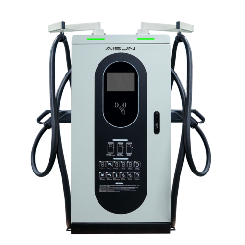
The existing low-voltage layer behaves differently, and that matters for phasing. A DC charger in the 30 to 480 kW range running on a 380 V three-phase input plus or minus 15 percent is a distribution-level load many sites can accommodate without a service rebuild. That is why the mid-power layer of a project usually moves first.
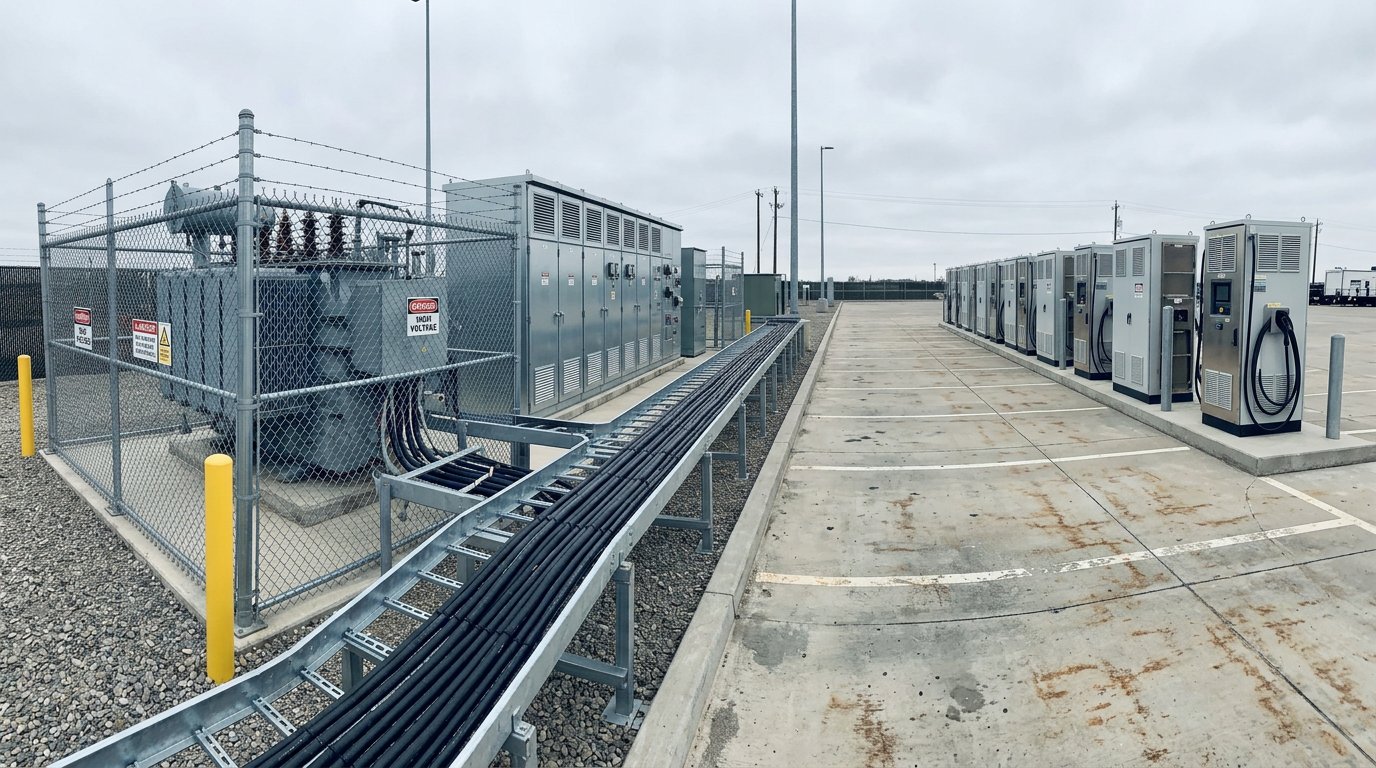
Transformer and switchgear installation beside a heavy vehicle charging apron
Cable, Connector and Cooling: The Part Drivers Actually Touch
Cooling earns its place through the physics. Current-carrying capacity is limited by the temperature the conductors and contacts can hold, and a passively cooled cable carrying megawatt current would be both too hot to handle and too heavy to lift. Liquid cooling lets a smaller conductor carry the same current inside the same temperature limit, which is what brings a megawatt cable down to a weight a driver can handle.
Two cooling architectures buyers conflate
Cable-only cooling is one architecture. Combined cable, connector and contact cooling is the other. The second holds contact temperature lower and sustains higher current, but it runs a coolant loop through the component that gets dropped, dragged and occasionally driven over. Neither is automatically better; they carry different service burdens and different failure modes, and the tender should name which one you are buying.
The coolant circuit is the maintenance item. Quick-couplers, hose routing, leak detection, coolant specification and service interval all belong in the supply contract, because a coolant fault can derate a bay or stop it outright. Cabinet thermal design matters for the same reason: heat rejected by the cable circuit has to go somewhere, and a cabinet that puts the power electronics in their own compartment with an independent cooling path holds those components inside their temperature window while the cable loop is working hard. Ask every supplier to demonstrate that arrangement in hardware and in test data: two cooling paths, an electronics compartment shielded from the cable circuit, and evidence that the electronics hold their rating at your site design ambient.
Handling, alignment and the holder that protects the inlet
The connector is large and the cable is heavy. A rotated connector holder that aligns the MCS connector with the truck inlet and removes cable torque protects that inlet, which is the expensive part to replace and the one that puts a truck off the road when it breaks. Ask how much insertion misalignment the connector tolerates, because a distracted driver at a truck stop is the normal operating condition rather than an edge case.
A truck stop works on the cable and connector continuously with sun, road spray, dirt and de-icing salt, and a stated ingress protection rating does not by itself tell you whether the cooling circuit stays sealed through winter. In cold regions, coolant viscosity and heater requirements change startup behaviour well below freezing, so ask for those numbers as part of the datasheet rather than meeting them during commissioning week.
Liquid-cooled megawatt charging connector resting in its holder with coolant hoses visible
Interoperability: What Mating and Certification Actually Guarantee
A connector that fits is not a system that works. MCS is a communication standard as much as a mechanical one, and the gap between the two shows up as a slow session rather than a fault code.
The power request travels over the high-level communication layer. Charger and vehicle must implement the same revision with the same optional features. A mismatch typically appears as a quietly capped session, which is far harder to diagnose than an error message and far more expensive to argue about at month end.
Conformance testing exists because compatibility claims are often self-declarations. CharIN runs conformance testing and interoperability events for exactly this reason. Ask for the test report and the date it was issued, not a sentence in a brochure.
Certification answers a different question. A UL or CE mark confirms the equipment meets a safety standard as built. It says nothing about whether it will talk to another vendor’s truck. Both matter, and a buyer who treats one as the other ends up with a safe charger that will not deliver full power.
Specify failure behaviour, not just the happy path. What does the charger do when the handshake times out, when the latch reports a fault, when coolant temperature crosses its threshold, and what does the driver see in each case? An opaque failure costs more in driver support calls than in parts.
Joint commissioning with the real vehicle is the only meaningful acceptance test at this stage of the market. Test against the actual tractor model you will operate, not a simulator, and make it a payment milestone rather than a paragraph in the handover file.
Firmware coordination runs for the life of the asset. Both ends will receive updates, and the support contract should say who owns compatibility. The network protocol question matters here too: if you are still choosing between OCPP 1.6 and OCPP 2.0.1 for your charging network, settle it before the megawatt bays arrive, because the back office is the only place a capped session becomes visible.
The RFQ Line Items That Separate Two 1 MW Chargers
Paste these fields into the tender. Each one changes the outcome rather than adding paperwork, and a supplier who cannot answer one of them has told you something useful.
Datasheet field
Why it decides the outcome
Continuous current at a stated ambient, plus the full derating curve to your site design temperature
A single peak amperage figure is not a specification. The curve is what your afternoon load actually follows.
Voltage range, with maximum current available at both the top and bottom of it
A truck’s pack voltage moves through the session, so the current capability at the low end sets the early ramp.
Cooling architecture, coolant type, service interval, leak detection method, and which parts of the assembly are actively cooled
This drives your maintenance contract and the spares you stock.
Connector configuration, cable length, management arm or holder, and stated insertion alignment tolerance
A single MCS outlet and a dual configuration with an optional CCS connector serve very different mixed fleets, and the holder protects the inlet.
Supported high-level communication revision, exposed open charge point protocol version, and fallback behaviour against an older vehicle revision
Compatibility is negotiated in software, not in the connector shell.
Session performance evidence: kWh versus time for a declared pack size, starting state of charge and ambient, plus efficiency at 25, 50 and 100 percent load
This is the only field that lets you compare two 1 MW products honestly.
Protection set documented individually, with trip thresholds and recovery behaviour
Over-current, under-voltage, over-voltage, ground fault, surge and overtemperature each need their own numbers. A protection count is marketing; documentation granularity is engineering. AiPower’s eight-layer protection scheme is a useful example of how specific that documentation can get.
Conformance test report, certificate numbers with their scope, and the revision each refers to
The scope page has to name the exact cabinet model and hardware revision you are buying. A rating earned by a sister model or an earlier revision does not transfer to the unit on your purchase order.
Service commitments: mean time to repair, spare module and coolant component availability, remote diagnostic access, firmware support window, warranty that survives a megawatt duty cycle
Uptime is bought here, not at the cabinet factory.
Physical and site facts: footprint, weight, cooling air path and clearance, acoustic noise at the bay, and whether the unit is an industrial charging station rated for a working truck yard
These get forgotten until installation day and then cost the most schedule.
Then score tenders on the derating curve and the session curve first. The headline kilowatt figure is a marketing column you can safely ignore until those two documents are on the table. Our EV charger RFP procurement checklist covers the commercial and contractual fields that sit around this technical core.
What to Specify Now, and What You Should Defer
Separate the irreversible decisions from the reversible ones and the project stops feeling like a single bet.
Lock now, because they are expensive or impossible to change later: site power capacity and the utility application, civil works and duct routes, bay layout and cable management, cooling system service access, and back-office integration. None of these get cheaper after concrete is poured.
Defer with confidence: the exact charger model and rating. Choose an architecture that lets you add bays or power capacity later, and accept that vehicle availability and tariff design will look different in two years than they do today.
Position MCS honestly inside the project. It is an en-route and corridor tool for trucks that cannot return to base. Most of a fleet’s energy will still move overnight at the depot on AC and mid-power DC, and a megawatt bay built for a duty cycle that ends at the yard every evening is capital doing nothing. The overnight charging design for 50+ vehicles is the layer where most of the cost and most of the savings actually sit.
Set the end-of-life expectation in the contract. Modularity and firmware support decide whether a charger bought in 2026 is still serviceable in 2032, long after the warranty has expired and long after the salesperson has moved on.
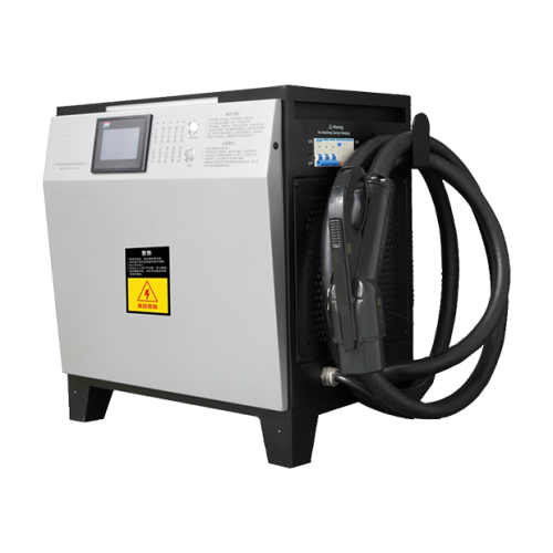
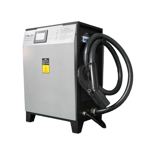
The megawatt bay gets the headline, but the depot layer where the energy and the cost sit is the part that can be specified and shipped today. evaisun supplies DC chargers from 30 kW to 480 kW on a 380 V three-phase input with documented multi-layer protection, AC chargers at 7, 11 and 22 kW on 230 V single-phase or 400 V three-phase, and industrial battery chargers for the yard equipment that moves alongside the trucks. Our team includes 60+ engineers, the products hold UL and CE certification, and we deliver to more than 30 countries from a 20,000 square metre production base. If you are scoping a site and want the non-megawatt portion quoted against your load calculation, send us the duty cycle and we will work from your numbers rather than ours.
Frequently asked questions
How much does a 100-kW charging station cost?
There is no honest single figure, because the charger is only part of the project. A 100 kW DC unit covers power modules, cabinet, connector and controls, but the installed cost also carries switchgear, cabling, civil works, the utility connection and commissioning. Ask for a project-level breakdown against your load calculation and get current utility and incentive figures from the utility programme itself.
What are some common problems with EV charging stations?
The recurring failures are cable and connector damage, coolant leaks on liquid-cooled assemblies, communication mismatches between charger and vehicle, and derating on hot days when the cabinet cannot shed heat. Downtime usually traces back to the service contract rather than the hardware: no spare power modules on site, no remote diagnostics, and no defined response time for a bay that is down.
Should you leave your EV plugged in all the time?
For the charging equipment it is harmless, and for a depot it is often how managed charging works. What matters is the pack, not the plug: a battery held at a high state of charge for long periods ages faster, so set a departure state of charge and let the charger schedule the session. Confirm the manufacturer’s guidance for the specific vehicle.
Subscribe the newsletter to get updated to news and promotions
Cookies give you a personalized experience,Сookie files help us to enhance your experience using our website, simplify navigation, keep our website safe and assist in our marketing efforts. By clicking "Accept", you agree to the storing of cookies on your device for these purposes. Click "Adjust" to adjust your cookie preferences.For more information, review our Cookie Policy