Why Some EV Chargers Fail Certification Testing — and How to Avoid Costly Redesigns
Home / Blog / Guidelines / Why Some EV Chargers Fail Certification Testing — and How to Avoid Costly Redesigns
14 Jul, 2026
certification failure redesign
EV charger EMC compliance
EV charger safety certification
UL 2594 EV charger testing
EV chargers fail certification testing most often because of decisions made months before the unit ever reaches a test lab — undersized thermal margins, inadequate EMC filtering, and grounding schemes that looked fine on paper but violate bonding requirements under load. These aren’t exotic edge cases; they’re the three failure modes that account for the vast majority of failed UL 2594, IEC 61851, or CE test reports we see across OEM projects. The good news: every one of them is preventable if you build compliance thinking into the design phase instead of treating certification as a final checkbox.
Thermal Design Is the #1 Certification Killer — Not Electrical Faults
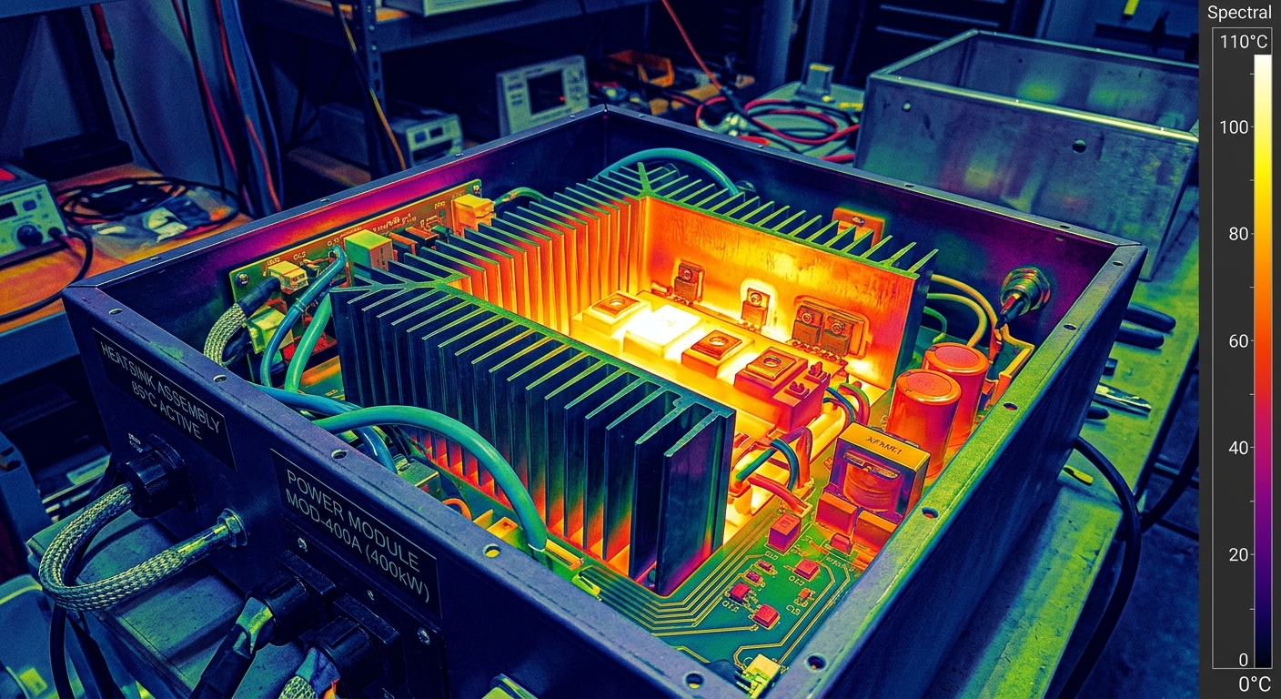
Here’s a stat that surprises a lot of procurement teams: more chargers fail on thermal derating and enclosure temperature rise than on any electrical safety parameter. Labs run chargers at rated load in a thermal chamber, often at 40°C ambient, and measure surface and internal component temperatures against limits set by UL 2594 or IEC 60950. If your heatsink was sized using a spreadsheet estimate instead of real airflow modeling, you’ll find out the hard way — after tooling is already cut.
A common mistake: engineers size the heatsink for the power module’s rated output but forget that the enclosure itself traps heat when mounted outdoors in direct sun with no shading calculation. This is exactly why DC fast chargers derate in summer even when they passed lab testing at room temperature — the lab conditions don’t always match field reality, and certification bodies are getting stricter about testing at the upper ambient bound.
What to check before layout freeze
Run CFD or at minimum a validated thermal simulation at your worst-case ambient, not room temperature
Model the enclosure as a closed system, not just the heatsink in isolation
Build in at least 15% thermal margin beyond rated continuous output
Thermal imaging view of EV charger heatsink and power module
EMC Failures: The Filter You Skipped to Save $3 Costs $30,000 in Retest Fees
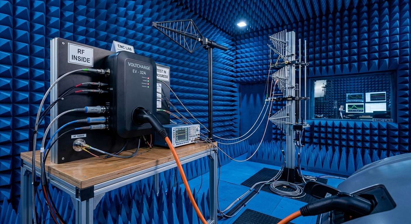
Electromagnetic compatibility (EMC) is where cost-cutting on the BOM backfires hardest. A conducted emissions failure at the test lab isn’t a quick fix — it usually means redesigning the input filter stage, which can mean new PCB traces, different inductor footprints, and sometimes a new enclosure to fit the larger filter components.
We’ve seen ODM partners try to shave a few dollars per unit by using a smaller common-mode choke than the reference design specified. It passed bench testing informally, but failed the formal conducted emissions scan between 150 kHz and 30 MHz by a wide margin. The redesign added 11 weeks to the program and required a second full test cycle — a cost that dwarfed what was saved on the component.
Practical EMC safeguards
Use pre-compliance scanning during prototyping, not just at final certification
Keep at least 6 dB of margin below the emissions limit line — not right at the edge
Treat cable shielding and grounding as part of the EMC strategy, not an afterthought
This ties directly into wiring quality more broadly — the same shortcuts that cause EMC failures often show up later as ground fault errors in outdoor DC chargers once units are deployed in the field.
EV charger unit undergoing EMC emissions testing in a shielded chamber
Grounding and Bonding: The Detail That Looks Fine on a Schematic and Fails in the Lab
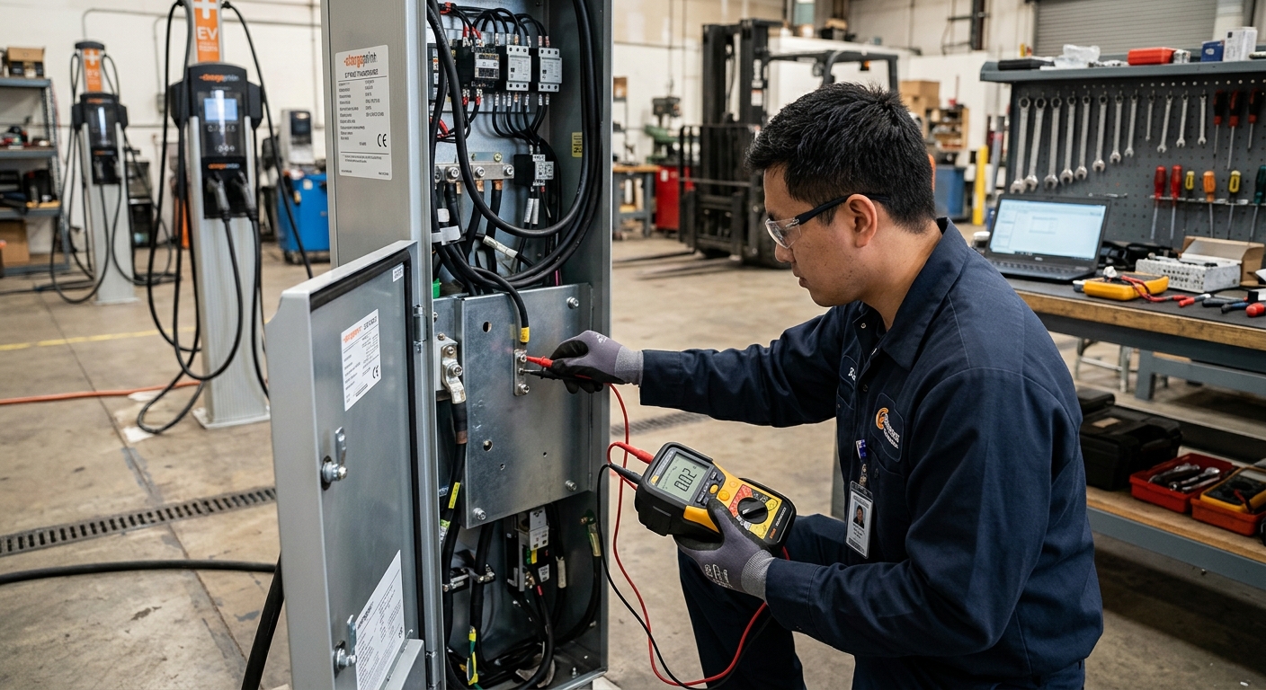
Grounding failures are frustrating because they’re rarely visible until a technician performs a bonding resistance measurement between exposed metal parts and the protective earth terminal. Standards typically require resistance under 0.1 ohms for accessible conductive parts. Painted enclosure panels, powder-coated brackets, or plastic standoffs between metal sections can quietly break that continuity even though the schematic shows a continuous ground path.
For instance, one distributor’s contract manufacturer used a painted mounting bracket to attach the charger’s internal chassis to the outer enclosure. The paint acted as an insulator. The unit passed every electrical safety test except bonding continuity — and the fix required removing paint from contact points and adding a bonding strap on every unit already built, a rework that hit hundreds of units already in inventory.
Design habit that prevents this
Specify bare-metal bonding points explicitly in the mechanical drawings, and verify continuity on the first-off sample before mass production tooling locks in — not after.
Technician measuring bonding resistance on an EV charger enclosure
Firmware Fault-State Timing Is an Overlooked Certification Trap
Certification standards don’t just test hardware — they test how fast and how consistently your firmware responds to fault conditions. IEC 61851 and UL 2594 both specify maximum response times for ground fault detection, overcurrent shutdown, and connector temperature cutoffs. If your firmware’s fault-detection loop runs at 500ms polling when the standard expects sub-100ms response for certain fault classes, you’ll fail functional safety testing even though the hardware sensors themselves work perfectly.
This is a subtle failure mode because it often passes basic functional testing — the charger does shut off eventually. The problem is the timing margin. Labs measure exact millisecond response times with oscilloscope traces triggered on fault injection, and there’s no partial credit for “close enough.”
Firmware-related certification issues connect closely to broader communication reliability — the same polling architecture that’s too slow for fault response is often the root of communication errors that plague EV chargers in daily operation.
Connector and Cable Assembly Failures Are More Common Than You’d Think
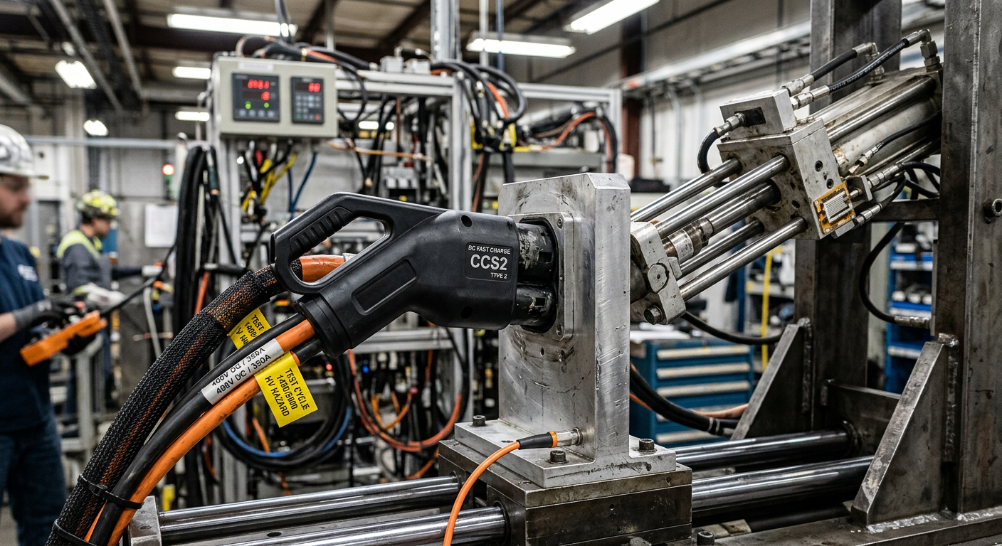
Mechanical durability testing — insertion cycle counts, cable flex testing, connector retention force — trips up more chargers than people expect, especially on DC fast charging units where cable weight and connector mass are higher. Standards typically require thousands of mating cycles without degradation in contact resistance. A connector that feels solid after 50 hand-tested insertions can start showing contact wear at cycle 3,000 in the lab’s automated test rig.
This is closely tied to cable thermal performance too. If your cable cooling design is marginal, repeated high-current cycling during mechanical testing can create localized heating that accelerates insulation wear — a compounding failure that shows up as two separate test report line items. For DC fast charger programs, it’s worth reviewing liquid-cooled versus air-cooled DC charging cable designs before committing to a connector and cable supplier.
DC fast charging connector undergoing mechanical cycle testing
Why Testing a Pre-Production Sample Instead of the Final BOM Backfires
One of the most expensive mistakes in the certification process isn’t a technical flaw — it’s a process flaw. Teams submit a hand-built pre-production sample for certification, then quietly swap a component during mass production for cost or supply-chain reasons. Even a “drop-in equivalent” capacitor or relay can change EMC behavior or thermal performance enough to invalidate the certification, technically requiring a re-test or at minimum a delta report.
This is a real risk in OEM/ODM sourcing relationships where the factory has its own approved vendor list that may shift between the certification sample build and full production. If you’re comparing sourcing models, this is exactly the kind of detail worth clarifying upfront — see our guide on OEM vs. ODM EV chargers for global distributors for what questions to ask before placing an order.
Lock the BOM before you submit for certification
Freeze critical components — power semiconductors, EMC filter parts, connectors — before building your certification sample, and require any post-certification substitution to go through a formal change control review with your test lab.
Building Compliance In From the Start Costs Less Than Fixing It Later
Every failure mode above shares the same lesson: the earlier you address it, the cheaper it is. A thermal margin adjustment during simulation costs a few hours of engineering time. The same issue caught during formal certification testing can cost six figures in redesign, retooling, and repeated lab fees — plus months of delayed market entry.
For distributors and project developers evaluating charger suppliers, this is a good filter question: ask to see the actual certification test reports, not just the certificate. A report shows margin data — how close the unit came to failing on emissions, temperature rise, and bonding resistance. Units that barely scraped by are far more likely to fail spot-check retesting or field variability than units with healthy margin. This kind of due diligence matters just as much as evaluating IP ratings and outdoor charger lifespan when qualifying a new supplier.
Subscribe the newsletter to get updated to news and promotions
Cookies give you a personalized experience,Сookie files help us to enhance your experience using our website, simplify navigation, keep our website safe and assist in our marketing efforts. By clicking "Accept", you agree to the storing of cookies on your device for these purposes. Click "Adjust" to adjust your cookie preferences.For more information, review our Cookie Policy