Why Ground Fault Errors Plague Outdoor DC Chargers — And the Wiring Mistakes Behind Them
Home / Blog / Guidelines / Why Ground Fault Errors Plague Outdoor DC Chargers — And the Wiring Mistakes Behind Them
23 Jun, 2026
outdoor EV charger wiring
GFCI nuisance trips
EV charger grounding mistakes
DC charger installation
Most ground fault errors on outdoor DC fast chargers are not hardware failures — they are wiring failures. The insulation monitoring device (IMD) inside the charger is doing its job perfectly; it is detecting real leakage current created by bonded neutrals, moisture intrusion in conduits, or shared ground electrodes that were never designed for high-frequency switching loads. Fix the install, and the “faulty” charger usually runs for years without another trip.
Here is what is actually going wrong on site, and how engineering teams and distributors can diagnose the root cause before swapping a perfectly good power module.
What the Charger Is Actually Measuring
Before blaming the install, you need to understand what triggers the error. A DC fast charger continuously monitors insulation resistance between the DC+ / DC– rails and protective earth (PE). The IMD typically trips below 100 Ω/V — for a 1000 V system, that’s around 100 kΩ. Anything lower and the contactors open.
The key insight: this measurement is extraordinarily sensitive. A damp conduit fitting, a single strand of stranded copper touching a grounded enclosure, or 50 mA of capacitive leakage from a long shielded cable can all push the reading past the threshold. The charger is not broken. It is telling you something is wrong outside its enclosure.
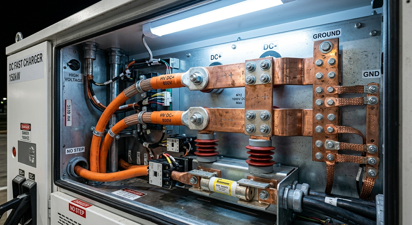
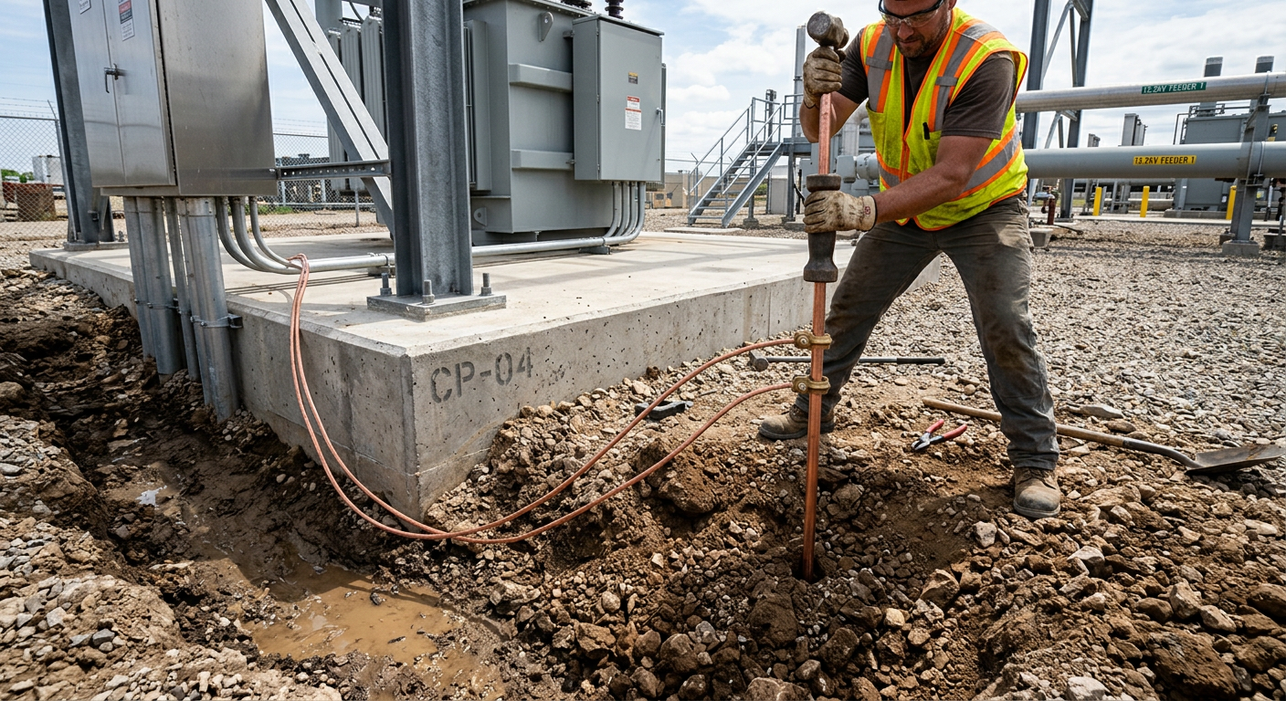
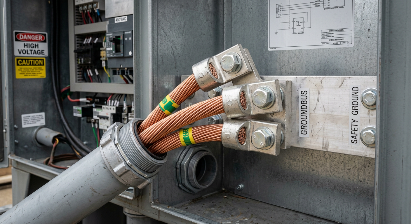
Internal wiring and busbars of a DC fast charger showing ground and DC connectionsCopper ground rod installation at an outdoor electrical site
Mistake #1: Bonding Neutral and Ground at the Charger
This is the single most common error we see in warranty returns. In a properly designed AC service, neutral and ground are bonded at exactly one point — the main service panel. Bond them again at the charger’s subpanel or inside the unit, and you create a parallel path for neutral current to flow through the equipment ground.
On a 480 V three-phase 180 kW charger pulling 220 A per phase, even a tiny imbalance pushes amps through the ground conductor. The IMD sees this as leakage, and trips. Worst part? It works fine during commissioning when loads are balanced and dry. Two weeks later, the first rainstorm reveals the problem.
For instance, a logistics operator in Rotterdam installed eight 120 kW chargers from a respected brand. Three of them threw ground faults intermittently. The fix was not a firmware update — it was removing the neutral-ground bond an electrician had “helpfully” added inside the disconnect.
Mistake #2: Sharing the Ground Electrode with Other Equipment
Outdoor DC chargers should ideally have a dedicated grounding electrode, or at minimum a properly bonded equipotential grid. When installers tap into an existing building ground that also serves VFDs, lighting, or other switching loads, high-frequency noise rides back into the charger’s PE conductor.
The IMD interprets HF noise as leakage. Resistance readings dance up and down, and you get the dreaded intermittent fault that disappears the moment a technician arrives with a meter. Use a dedicated ground rod with measured resistance below 5 Ω, and run a separate, low-impedance PE conductor sized for the fault current — not just the minimum code minimum.
Mistake #3: Conduit Sealing That Looks Right But Isn’t
Water does not need to pour into a conduit to cause ground faults. Moist air entering a warm conduit and condensing on cool conductors is enough. We’ve seen brand-new installations fail within a month because installers used standard threaded fittings without sealing compound on the line side, and skipped drain fittings at the low point.
Best practice for outdoor DC charger feeders:
Apply electrical duct sealant at every conduit entry into the charger cabinet
Install a drain fitting at the lowest point of the conduit run
Use Type-LB or sealing hubs rated for the environmental class
Pressure-test conduits during commissioning if the site is humid or coastal
NEC 250.122 and IEC 60364-5-54 both specify minimums for protective earth conductors, but minimums are sized for fault clearing — not for the millisecond-scale transient currents a DC charger’s EMI filter dumps to ground. A 180 kW charger with a 16 mm² PE conductor on a 30 m run can develop several volts of common-mode noise between charger PE and source PE.
The fix is simple but routinely ignored: oversize the PE conductor to at least match the phase conductors on runs over 20 m, and use stranded copper rather than aluminum. On long runs, consider a separate equipotential bonding conductor between the charger and the dispenser if you’re using a split architecture, as detailed in our breakdown of power module architecture in 360 kW chargers.
Thick stranded copper PE conductors terminated at a charger cabinet
Mistake #5: Cable Shield Termination Done Both Ends Without Coordination
Shielded power cables between rectifier cabinets and remote dispensers need careful shield handling. Terminate the shield at both ends and you create a ground loop carrying tens of milliamps of circulating current. Terminate at only one end and you get HF noise injected into the DC side.
The correct approach for most outdoor DC architectures is a 360° shield bond at the source cabinet, a high-frequency capacitive bond at the far end, and a separate green-yellow PE conductor for safety grounding. Skipping this distinction is one of the most common reasons IMD readings drift over the first months of operation.
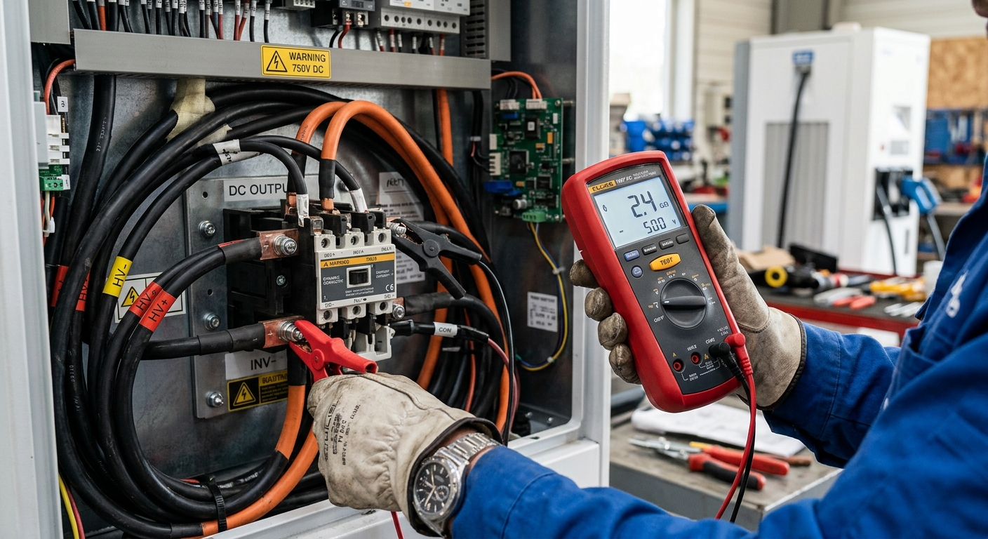
Technician using insulation resistance tester on EV charger wiring
Diagnosing the Real Problem in Under 30 Minutes
When a customer calls with repeated ground fault errors, do not ship a replacement unit. Walk them through this sequence first:
Read the IMD log. Most chargers store insulation resistance trend data. A slow drift down over days points to moisture. A sudden drop points to a wiring change or vehicle issue.
Disconnect the EV. If the fault clears, the vehicle’s high-voltage system or the charging cable is the source — not the charger.
Measure neutral-to-ground voltage at the disconnect. Should be under 2 V. Higher means improper bonding upstream.
Megger the feeder cables to PE with the charger disconnected. Below 100 MΩ means moisture or damaged insulation.
Verify ground rod resistance. Above 5 Ω is suspect on a high-power site.
For a comparable diagnostic flow on a related issue, see our guide to EV charger communication errors — many sites that have ground fault problems also have communication problems, and the root cause is often the same: poor grounding.
What This Means for Distributors and OEM Partners
If you’re a distributor, ground fault complaints are your single biggest field-service cost. The unit that gets RMA’d almost always tests fine on the bench. That’s because the problem was never the charger — it was the install. Investing in installer training and a simple commissioning checklist cuts these calls by more than half.
For OEM partners specifying chargers for large rollouts, push for units that expose IMD trend data via OCPP — not just a binary fault flag. Being able to see insulation resistance over time turns a mystery callout into a 10-minute remote diagnosis. We discuss similar reliability considerations in our overview of the hidden cost of cheap EV chargers.
Building Ground Faults Out of Your Next Project
The pattern is consistent across every market we ship to: ground fault complaints cluster around installers who treat a DC fast charger like an oversized AC appliance. It isn’t. The IMD is a more sensitive instrument than most electricians have ever worked with, and it punishes shortcuts that would be invisible on a standard panel.
If you’re scoping an outdoor DC charging deployment — whether that’s a fleet charging station or a public corridor site — get the grounding scheme reviewed before the concrete is poured. It’s the cheapest part of the project to fix on paper, and the most expensive to fix after commissioning.
If you’d like our engineering team to review your site grounding plan or recommend chargers with deeper diagnostic visibility for your next deployment, get in touch. We’d rather help you build it right than process the warranty claim later.
Subscribe the newsletter to get updated to news and promotions
Cookies give you a personalized experience,Сookie files help us to enhance your experience using our website, simplify navigation, keep our website safe and assist in our marketing efforts. By clicking "Accept", you agree to the storing of cookies on your device for these purposes. Click "Adjust" to adjust your cookie preferences.For more information, review our Cookie Policy